The designs in this section represent several years of working with PVC and copper fittings and also many ideas from builders I have corresponded with. I have selected my favorite versions and removed some of the older postings. One of the first negative comments that I received regarding the 20-20 design in 2001 was the perception that it was "Flimsy". I don't think it was so in that it was not intended to to be a strong or long lasting model. It was, and is, intended to help sailors experience the joys of self-steering with minimal expenditure of time or material. However, I found that many who were interested in building one wanted to build a model for real sea going use. I think these designs will do that. The perception that copper is "Soft and weak "is going to take some explaining. I have done tests and stress analysis to convince myself of the benefits of these designs. See below.
Think of these designs as a simple way to get a rugged model without having to build in stainless steel. I have not yet included CAD drawings of these ideas on the assumption that anyone wanting to tackle these designs will have the level of skill to build from just the scanned sketches and related photos. If you would like the CAD files that these JEPG files were scanned from please contact me.
These designs have been built as prototypes and were used to evaluate the construction methods using PVC and copper plumbing parts. They have had limited sailing time but seem to work well.
Two of these designs are based on ideas presented by Jan Alkema in several boating publications but in my opinion have not had the publicity they deserve. The USD (up side down) vane is a concept that improves performance and the RHM (rudder head mount) is a fine solution to mounting a pendulum type device on outboard or transom rudders. It is a challenge to understand but once you see the elegant simplicity of the scheme I think you will agree.
Model 2004 November 2003
I consider this a logical evolution of the 20-20 idea of a cheap, easy to build self-steering design that will allow the sailor with normal hands on skills to build a device that that will have very good performance and be capable of rough water use.
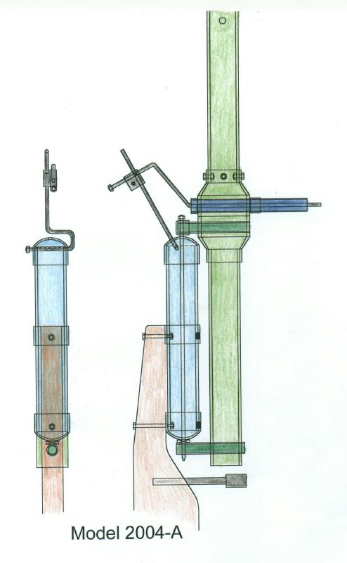
 Model 2004-A Model
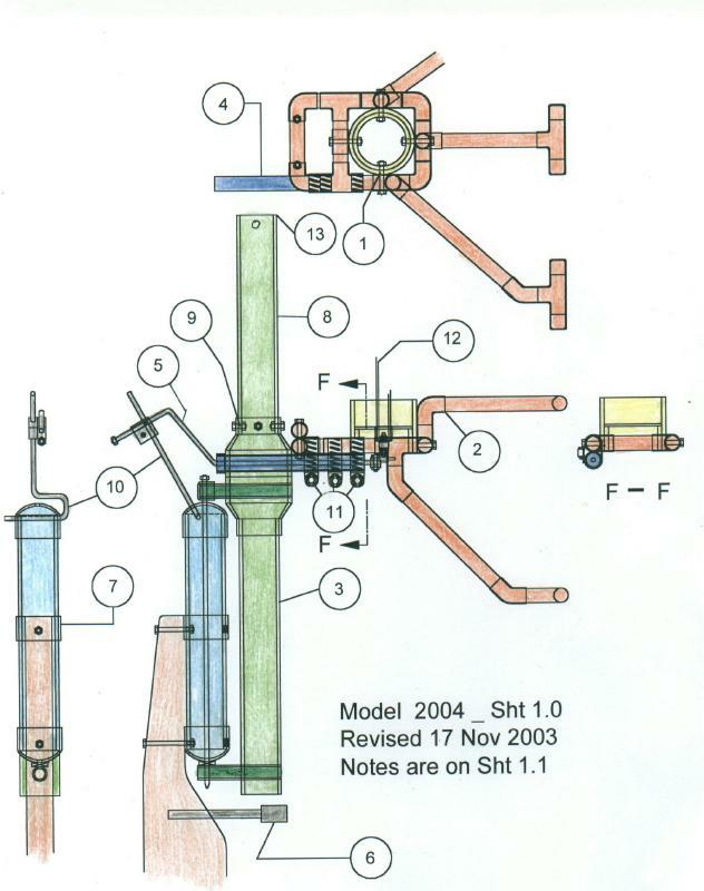
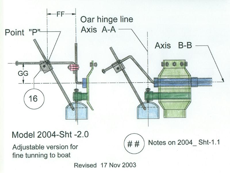
2004_1.0 Model 2004_2.0
Model 2004-A Model
2004_1.0 Model 2004_2.0
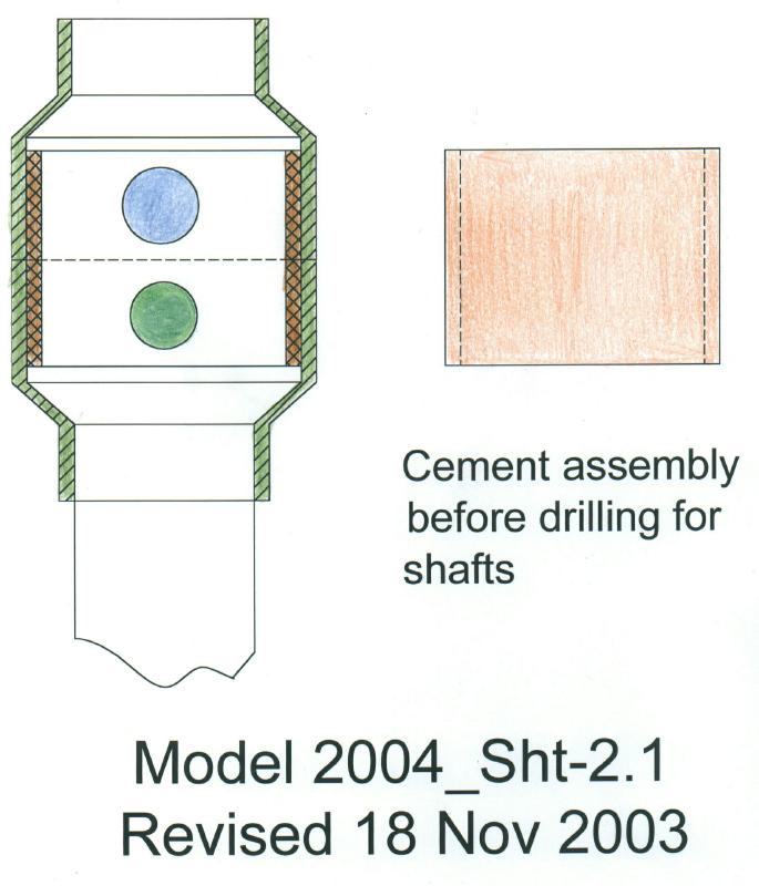
 Model 2004_2.1 Model
2004_3.0 Model 2004_4.0
Model 2004_2.1 Model
2004_3.0 Model 2004_4.0
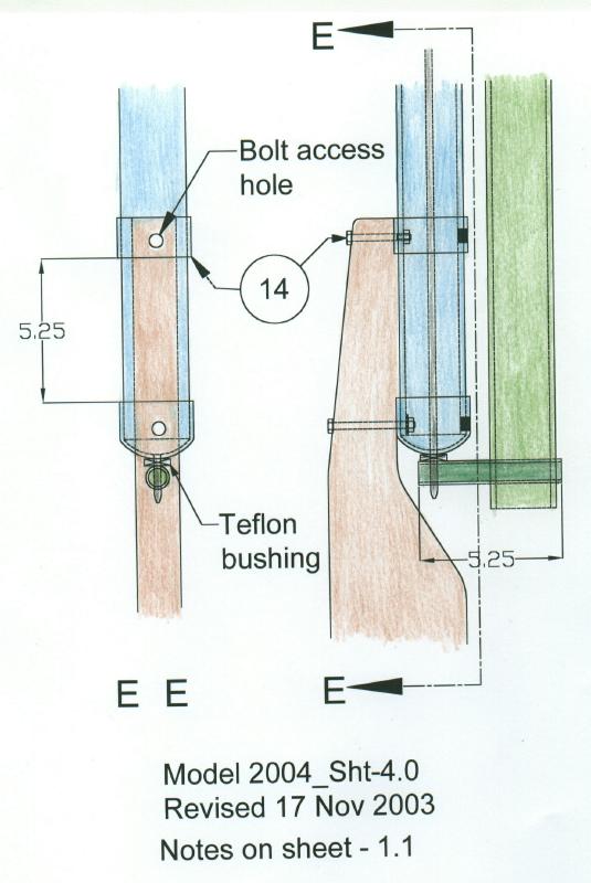
![]() Model 2004 notes
Model 2004 notes
 This version obviously reflects my experimentation with PVC
and copper parts. It also provides some features that have
been needed such as --
A way to quickly stow the oar out of the water
when using a motor to move the boat in reverse around docks
or mooring piling . The entire oar and it's carrier will rotate to
a vertical position without removing or disengaging any lines
or fittings. Just rotate the oar to starboard until it points up
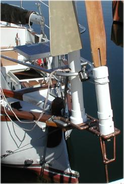
and tie it off in the inverted position. A photo of similar design
shows how it worked on my boat.
This version obviously reflects my experimentation with PVC
and copper parts. It also provides some features that have
been needed such as --
A way to quickly stow the oar out of the water
when using a motor to move the boat in reverse around docks
or mooring piling . The entire oar and it's carrier will rotate to
a vertical position without removing or disengaging any lines
or fittings. Just rotate the oar to starboard until it points up
and tie it off in the inverted position. A photo of similar design
shows how it worked on my boat.
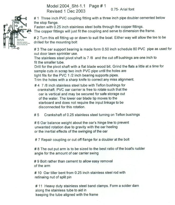
The model 2004 oar carrier is based on simple PVC fittings and simple input linkage from the wind vane. The support frame is copper pipe and soldered fittings for a rugged mounting base that is easy to build and very inexpensive. No special tools or construction skills are needed.
Photos to be added here showing prototype construction details
Combining these water side parts with a USD wind vane should produce a system to steer most boats better than many commercial products and do it for a fraction of the cost.
Model 90-95
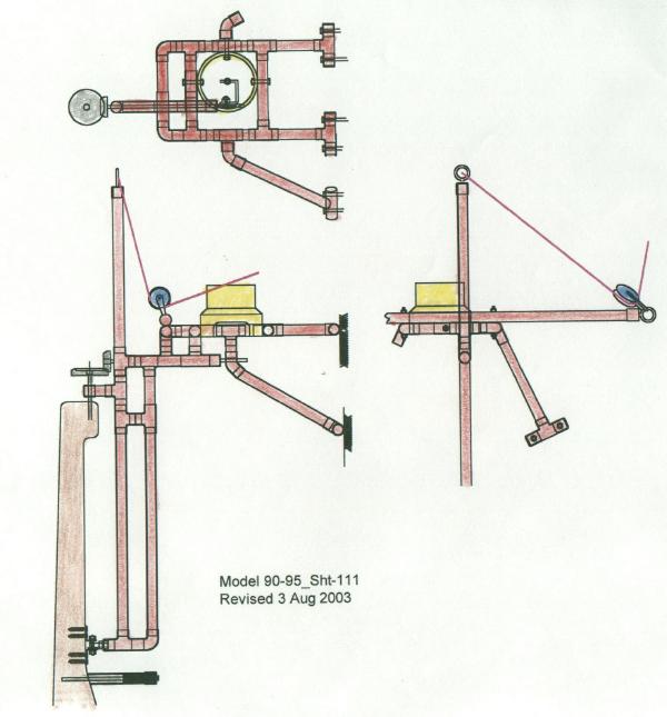
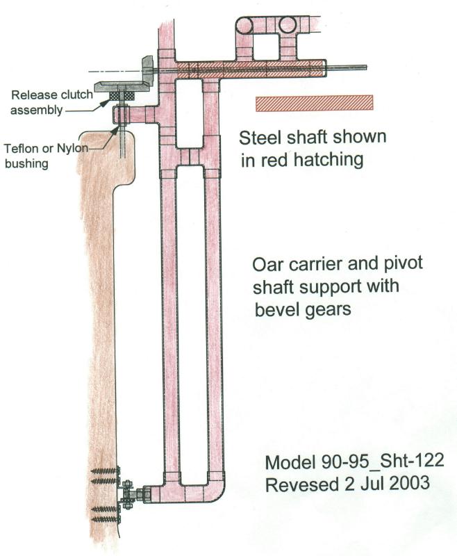 Bevel gears to allow rotation of carrier
to a safe stowage position. Shown here with a copper oar carrier
and hinged oar.
Bevel gears to allow rotation of carrier
to a safe stowage position. Shown here with a copper oar carrier
and hinged oar.
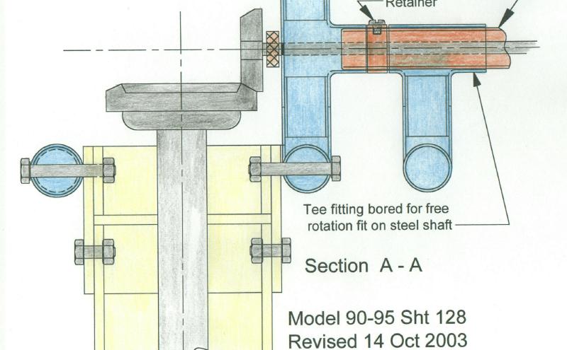 The 90-95 design with
copper tee fittings will require the removal of the stop material in
three fittings to allow the shaft to pass through. This is easy for a lathe
but can be done by hand with a round file or rotary bit and a hand
drill.
The 90-95 design with
copper tee fittings will require the removal of the stop material in
three fittings to allow the shaft to pass through. This is easy for a lathe
but can be done by hand with a round file or rotary bit and a hand
drill.
Model 90-93 Jan Alkema invention---- RHM
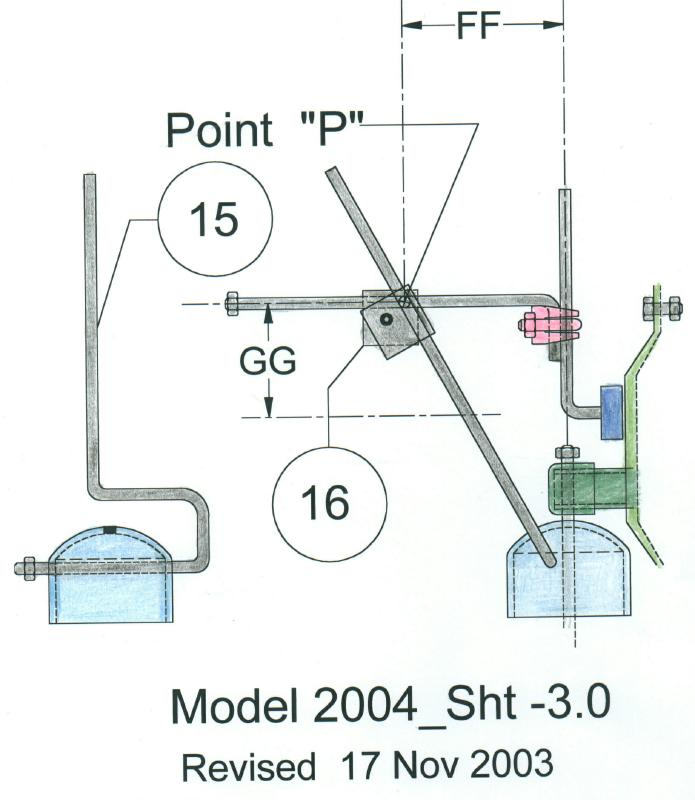
The sketch below shows the basic idea and the numbers are typical values. Several linkage arrangements have been used. The original model uses small wire rope from the vane.
Check the last of this page for a write up he did for Practical Boat Owner The publisher has no objection to the use of the material here.
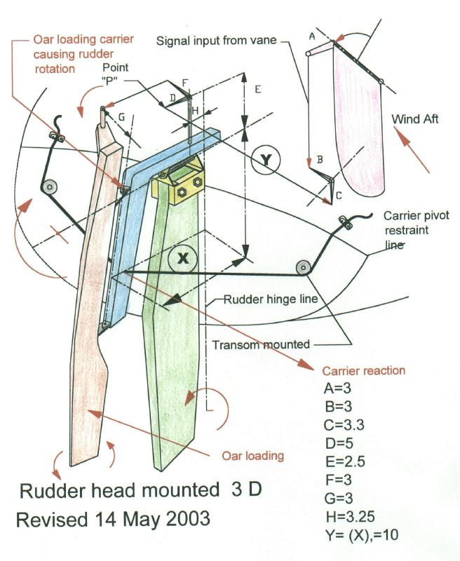 I refer to this as a RHM for rudder head mount.
This idea is for transom
mounted rudders and has no lines in
the cockpit or to the tiller.
This concept of Jan's is hard to
visualize at first look
but it is a really unique scheme that he
has used with much
success for many years. The line to the
blue carrier I call
a " Floating link ". It acts to provide a pivot
point about which the oar
load is reacted. This causes the
upper hinge of the oar to
load the carrier hinge causing a
torque on the rudder. To
disconnect the gear ,the lines are
released at the
cleats and the oar will then trail along.
A rigid link
with self aligning ends will do the same function
and might be
used to clear an outboard motor or swim
platform.
I refer to this as a RHM for rudder head mount.
This idea is for transom
mounted rudders and has no lines in
the cockpit or to the tiller.
This concept of Jan's is hard to
visualize at first look
but it is a really unique scheme that he
has used with much
success for many years. The line to the
blue carrier I call
a " Floating link ". It acts to provide a pivot
point about which the oar
load is reacted. This causes the
upper hinge of the oar to
load the carrier hinge causing a
torque on the rudder. To
disconnect the gear ,the lines are
released at the
cleats and the oar will then trail along.
A rigid link
with self aligning ends will do the same function
and might be
used to clear an outboard motor or swim
platform.
I suggest that a simple model will reveal the action of the oar on the rudder. The oar is not a trim tab as it might appear. Since the oar is rotating with the rudder a negative feed back is required to compensate for the angle of incidence and if needed provide more negative rotation to provide stability. Fin keels and rudders without a skeg on many boats is a challenge for many self-steering devices but his one has proven that it capable .
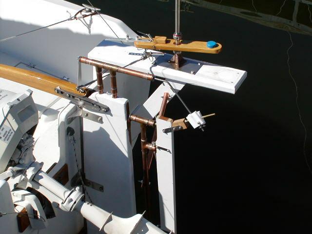 A side mounted vertical vane connected to a rudder head that required only minor work for
the support shaft of a simple carrier design. The builder converted to this arrangement from
a trim tab system.
A side mounted vertical vane connected to a rudder head that required only minor work for
the support shaft of a simple carrier design. The builder converted to this arrangement from
a trim tab system.
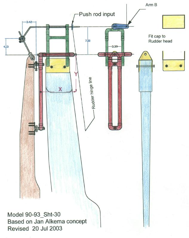
This is a simple linkage and oar carrier that will allow the push rod input from the wind vane to be from any direction. This means that the vane can be mounted off to one side or above if mounting space is a problem. The small displacement of the crank input point due to the rudder turning will have minor effect on the oar.
 Model 90-93_Linkage-3
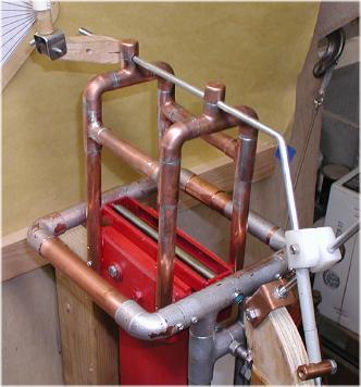
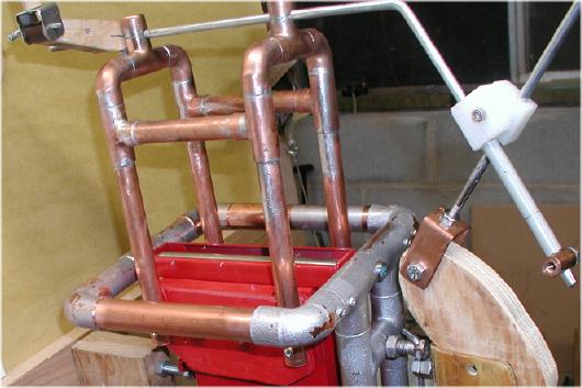
This is the linkage shown mounted to the
red mock up rudder head. It is driven by the input arm
at the rear and turns the oar through the sliding plastic
( Teflon or Nylon ) blocks. The supporting trestle
is made of one half inch copper pipe and screw fastened
to the rudder head.The push rod input from the vane is
located near the rudder hinge line to minimize any unwanted
input to the oar tiller.
Model 90-93_Linkage-3
This is the linkage shown mounted to the
red mock up rudder head. It is driven by the input arm
at the rear and turns the oar through the sliding plastic
( Teflon or Nylon ) blocks. The supporting trestle
is made of one half inch copper pipe and screw fastened
to the rudder head.The push rod input from the vane is
located near the rudder hinge line to minimize any unwanted
input to the oar tiller.
 Model 90-93_Linkage-5
This shows the oar carrier pivoting on a stainless
steel tube supported by a fitting fastened to the
rudder head.
Model 90-93_Linkage-5
This shows the oar carrier pivoting on a stainless
steel tube supported by a fitting fastened to the
rudder head.
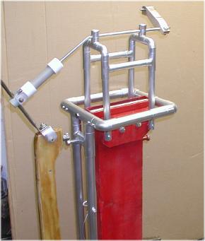 Model 90-93_Pic-9 with another oar tiller/crankshaft
fitting and painted with aluminum spray paint to look like stainless.
Model 90-93_Pic-9 with another oar tiller/crankshaft
fitting and painted with aluminum spray paint to look like stainless.
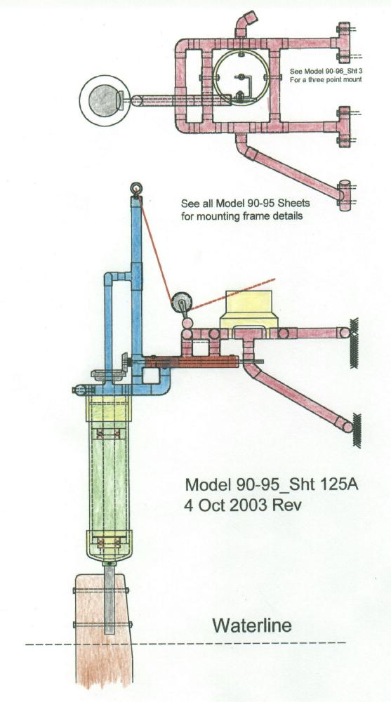
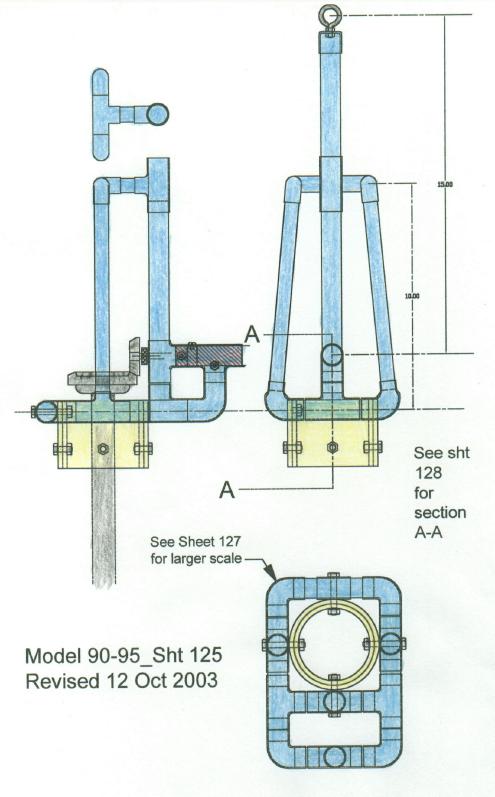
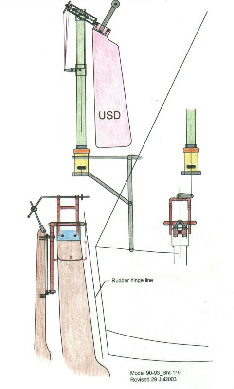 Model 90-93_Sht-110
The supporting frame for the USD vane uses the same
material and techniques as the other copper frames
and is attached to the boat's stern rail.
Model 90-93_Sht-110
The supporting frame for the USD vane uses the same
material and techniques as the other copper frames
and is attached to the boat's stern rail.
Model 90-94 USD vane system--- Another Jan Alkema
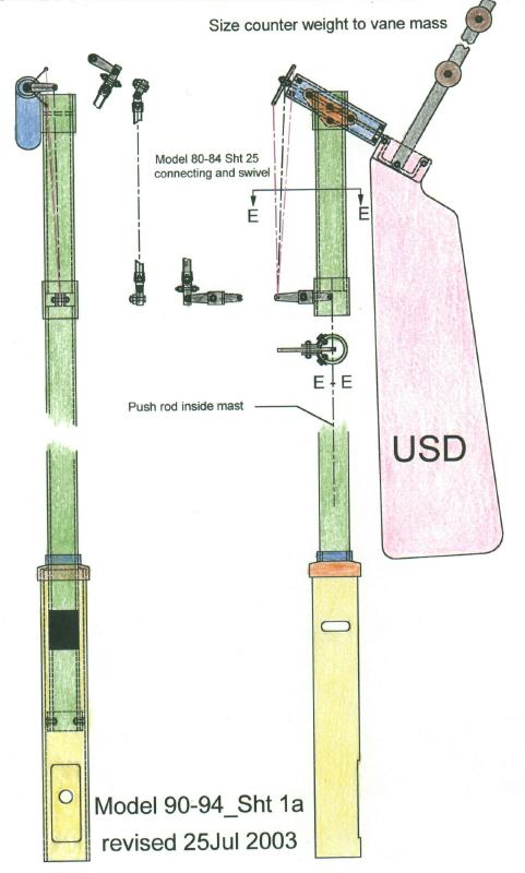 Model 90-94 _Sht 1a.
This USD design is recommended for all models.
The details are from other pages and the course setting is shown in detail on the
20-20 pages with photos and drawings. This version uses a larger base to adapt to the
copper frames. The push rod and vane linkage has proven to work very smoothly.
Model 90-94 _Sht 1a.
This USD design is recommended for all models.
The details are from other pages and the course setting is shown in detail on the
20-20 pages with photos and drawings. This version uses a larger base to adapt to the
copper frames. The push rod and vane linkage has proven to work very smoothly.
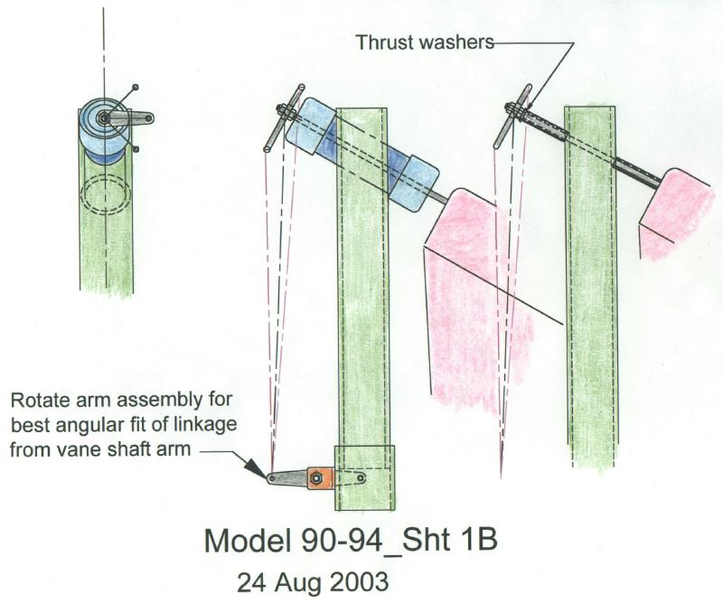 Model 90-94_Sht 1b
The tilted vane shaft carrier is made from 1-1/2 inch
(USA ) PVC pipe. A 1-7/8 hole saw makes a perfect
fit through the 2 inch mast. Very minor trimming may
be required if the holes are not exactly aligned.
Press fit the two and use Pvc caps for the shaft
bearings. Ball bearings could be used here but the
PVC will be quite satisfactory.
The simple shaft through the mast post is returning
to the 20-20 level ( Bird House Technology ) that has produced
many very satisfactory gears for builders world wide.
Model 90-94_Sht 1b
The tilted vane shaft carrier is made from 1-1/2 inch
(USA ) PVC pipe. A 1-7/8 hole saw makes a perfect
fit through the 2 inch mast. Very minor trimming may
be required if the holes are not exactly aligned.
Press fit the two and use Pvc caps for the shaft
bearings. Ball bearings could be used here but the
PVC will be quite satisfactory.
The simple shaft through the mast post is returning
to the 20-20 level ( Bird House Technology ) that has produced
many very satisfactory gears for builders world wide.
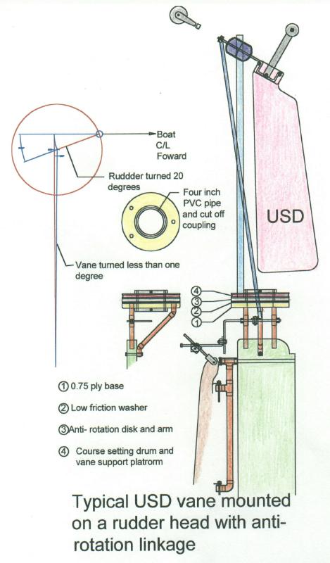 This is taking the RHM and USD ideas to combine in
a unit with all mounted to the boat's rudder. The turntable mount
is restrained in rotation by an arm as shown in the diagram layout.
the rudder turns per the normal RHM but the USD assembly is
not allowed to follow or rather maintains it's set direction except for
the minor and insignificant amount shown.
The weight of the USD parts and their supports can be built to
be less than 15 Pounds. It can also be built to be quickly removed
from the rudder as a unit.
The direct push rod from the vane crank to the crankshaft arm
will avoid slack wires or difficult adjustments and of course allow a full
360 degree course setting rotation.
This is taking the RHM and USD ideas to combine in
a unit with all mounted to the boat's rudder. The turntable mount
is restrained in rotation by an arm as shown in the diagram layout.
the rudder turns per the normal RHM but the USD assembly is
not allowed to follow or rather maintains it's set direction except for
the minor and insignificant amount shown.
The weight of the USD parts and their supports can be built to
be less than 15 Pounds. It can also be built to be quickly removed
from the rudder as a unit.
The direct push rod from the vane crank to the crankshaft arm
will avoid slack wires or difficult adjustments and of course allow a full
360 degree course setting rotation.
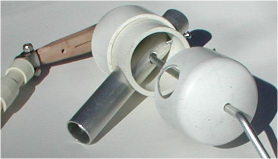 Vane support made from PVC cap fittings
mounted on aluminum post. Opened for photo showing over
sized hole in tube to clear crank rod which turns in the PVC caps.
Vane support made from PVC cap fittings
mounted on aluminum post. Opened for photo showing over
sized hole in tube to clear crank rod which turns in the PVC caps.
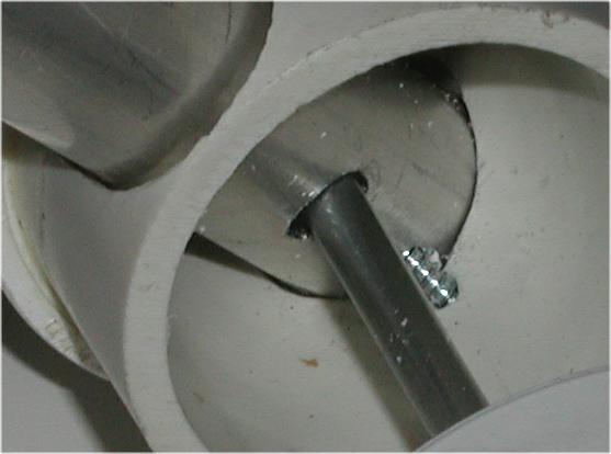 Close up of retaining screw in mast post
Jan's explanation of the rudder mounted design.
An innovative pendulum system for outboard rudders.
Jan Alkema
03-05-2005
Preface
On boats with outboard rudders it can be troublesome to install a pendulum windvane system. The pendulum has to be free of the rudder and should not limit the rudder movements from full port to full starboard. That means that an extended support frame will be necessary. It will put extra weight on the transom. Another obvious drawback is that the wind vane system has to be mounted further aft of the boat, which makes it more vulnerable in harbors and crowded marinas.
A lot of sailing boats with an outboard rudder and wind vane system make use of a trim tab, directly mounted at the rudder. The trim tab works as a servo system to generate enough force to turn the rudder.
It is unquestionable that a trim tab with the right dimensions works, but on some points its performance is less than that of the pendulum system.
Trim tab or pendulum.
Lets compare the characteristics of a trim tab and a pendulum system and focus on the following aspects :
- Steering torque
- Steering efficiency
- Yaw damping
- Support and vulnerability
- Obstructions in the cockpit
Steering torque.
The trim tab can be situated just at the trailing edge of the rudder or at some distance of it. This choice is mostly depending on the shape of the rudder. In figure 1. the trim tab is directly mounted after the trailing edge. In figure 2. the trim tab is mounted some distance behind the rudder.
In both cases the trim tab is working in the wake of the rudder. The solution of figure 2. has the advantage of giving a bigger torque, due to the increased distance between trim tab and rudder hinge.
The pendulum has normally a larger power arm as can be seen in figure 3. So the pendulum with the same dimensions of the underwater part as the trim tab, delivers more torque. This can be advantageous for heavy or unbalanced rudders. Pendulums can operate these rudders without problems, but trim tabs can be limited in their steering torque.
Steering efficiency.
A trim tab develops a force which direction is opposite to the rudder force. The trim tab is decreasing to some extend the effect of the rudder. With normal dimensions the loss of rudder force is approx. 10 %. So the trim tab makes the rudder less effective.
The pendulum force works in the same direction as the rudder, so it assists the rudder and increases the total rudder action and hence the steering efficiency.
Yaw damping.
Yaw damping is the ability to prevent or reduce oscillations in the course. Lack of this ability gives a zig - zag course, so it is an important characteristic of a course controller.
Yaw damping is not easy to explain, but the following example may help to get an idea of it. In this example we are only considering the influence on the rudder and we suppose that the vane is not turning during the yawing motion of the boat.
When wave and/or sail forces are turning the boat (yawing), then there will be pressure on the rudder from the water flow.
When the rudder is fixed a force is developed on the rudder which counteracts the yawing motion.
When the rudder is free, then it will line up with the water flow and does not give any counter force to the yawing motion.
A rudder with a trim tab is not fixed or free but controlled by the trim tab. When the boat yaws the water flow creates a force on the rudder + trim tab and initially the rudder tends to line up with the water flow and rotates a bit. But the trim tab gets a greater rotation (in the same direction) due to the linkage between trim tab and wind vane. The water flow on the deflected trim tab creates a force which prevents the rudder from lining up with the water flow. As a result of it the rudder gives some counter force, which damps the yawing motion.
This counter force is however smaller than a rudder alone, that had been fixed.
A pendulum system, connected to the rudder can give more yaw damping , and most when the pendulum is far aft of the rudder out of the wake. When the boat yaws the rudder and the pendulum get a pressure from the incoming water flow. The pendulum wants to swing out and the rudder wants to line up with the water flow. But because the pendulum is much more powerful then the rudder it swings out and turns the rudder opposite to the water flow direction. So instead of limiting the rudder angle from giving in (this is what the trim tab is doing), it increases the rudder angle to create an increased counter force. So the pendulum system gives a powerful and active yaw damping. The counter force of a rudder + pendulum is bigger than a rudder alone that had been fixed.
This is true when the pendulum is out the wake of the rudder. When the pendulum is close to the rudder then the active yaw damping effect is less. But it is always more than from the trim tab, because when the pendulum swings out, it brings the blade far more out of the wake of the rudder compared with the trim tab.
Support and vulnerabilityAn advantage of a trim tab system is that no heavy support is necessary. The trim tab is directly mounted at the rudder.
The trim tab is well sheltered by the rudder which is an advantage compared with a pendulum, which swings out and can pick up weed, ropes and floating debris
As already mentioned an extended support frame is inevitable for the normal pendulum system for an outboard rudder.
Obstructions in the cockpit.
The trim tab system has no steering lines and blocks to the tiller or wheel. The trim tab directly controls the rudder blade.
For normal pendulum systems steering lines with several guiding blocks are running through the cockpit to operate the helm or the steering wheel. This is mostly a nuisance in the cockpit.
Combining the advantages.
My boat, a Westerly Konsort, has an outboard rudder. When I started to design a wind vane system I wanted to have the best of both worlds. So the advantages of a pendulum system should preferably be combined with the advantages of a trim tab system. Would that be possible?
After many sketches and a lot of thinking I came up with a system which I later named the Rudder Head Mounted (RHM) pendulum or oar system. See the sketch in figure 4.
The pendulum has the horizontal hinge mounted on the rudder head.
Essential are the two restraint lines from the transom side to the oar carrier or pendulum tube. When these lines are loose, the pendulum can swing to each side, but it can not turn the rudder. The system is disconnected. When these restraint lines are tight, then they form a fixed point on the tube which will be a pivot point. (point P) When the pendulum swings out then the rudder is forced to turn.
Figure 5 shows how the swing out movement of the pendulum gives a rudder movement, when the restraint lines are tight.
For stretching or adjusting the restraint lines I use clam cleats on the aft cockpit sole. To release the lines, simply pull them out of the cleats.
This Rudder Head Mounted (RHM) pendulum combines all the advantages of both the pendulum and trim tab :
- It is a true pendulum with the power of normal pendulums.
- It increases the rudder action.
- Yaw damping is better than with a trim tab
- No heavy support frame is necessary.
- There are no steering lines in the cockpit
- One minus point remains. The pendulum is not so well sheltered after the rudder as the trim tab.
I made the prototype of the oar carrier and the oar from plywood. I used SS hinges which are normally used for the rudders of small dinghys. The first sailing tests were carried out in 1981 and it worked from the start. Figure 6 shows the prototype of the oar carrier and oar, which fitted very well with the shape of the rudder.
This RHM pendulum system is combined with a separate wind vane which is mounted on the push pit. Via thin stainless steel cables the rotation of the vane is transmitted to the little tiller on the oar.
Figure 4 shows how the cables are running from the wind vane to the small tiller arm on the oar.
I used the prototype of the RHM pendulum for some 5 years. After that I have rebuilt the system, using stainless steel tubes. Ball bearings are used for the oar rotation and in all blocks to get as low friction as possible. I also made the blade retractable. It is still in use, after 20 years, with only small modifications up to now. See figure 7 and 8.
Position of the cleats for the restraint lines.
The position of the cleats should be close to the sides, using the full width of the transom. The restraint lines have to remain reasonable tight without slack or over tension for rudder angles of +/- 20 degrees, which is the max. range for rudder corrections during sailing.
On my boat it appeared that the cleats should be positioned higher than the connection point P on the oar carrier or pendulum tube. On my system the vertical distance between P and the cleats is about 0.25 m.
In general it may need some trial and error to find the best positions of the cleats.
Well mannered behavior.
On every pendulum system the oar needs feedback, otherwise the system will over steer. When the oar is initially turned by the vane, it will swing out, but during that swing the oar is rotated back, to arrive at a certain swing angle and so at a certain rudder angle. The information of the swing angle is fed back in the turning of the oar through the linkage between vane and oar.
The RHM pendulum system needs more feedback than a normal pendulum, because the pendulum rotates together with the rudder, so that rotation must also be compensated as an extra.
The geometry of the cross beam and wires and blocks however ensures that there is more then enough feedback in the system, to get a well mannered behavior of the pendulum without any sign of over steering.
The system gives a good yaw damping in downwind and broad reaching courses on a lively boat like the Westerly Konsort. Note the straight track on figure 9 during a running course in force 5.
On windward courses the system works also very well.
Note the oar at work, most of the time out of the wake of the rudder in figure 10.
The wind vane part.
Up until now the wind vane part has not been highlighted. The wind vane part has been developed separately from the pendulum.
Before starting with the RHM pendulum I used a big wind vane, directly coupled to the rudder. I had taken that wind vane from my previous boat. It had an adjustable vane axis tilt angle. An article on that separate wind vane has been published in PBO nr. 170 Febr. 1981.
After building the RHM pendulum I combined it with the existing wind vane. The combination worked very well, although the vane was a bit oversized for operating the small oar.
Some 6 years ago I designed a new type of wind vane, the Up Side Down (USD) wind vane, which could easily be connected to the existing RHM pendulum via the thin stainless steel wires.
See figure 11.
The interesting feature of the USD vane is that the vane action increases when the boat heels. It automatically adapts its action in the right way to the sailing circumstances.
When heeled with some weather helm, the USD vane gives more action for a better accuracy. On a downwind course with no heel the USD vane action is less, which enhances course stability.
The USD wind vane has been described in the article Which wind vanes work best (PBO nr. 414 , June 2001).
How to operate the RHM / USD system.
At the start the vane is locked is a vertical position and the restraint lines are slack, the blade is put into the water. It appears that the oar is following the rudder without swinging out, also when the boat is steered manually. With slack restraint lines no forces are exerted on the rudder.
When the restraint lines are tightened and the vane is set on the desired wind course and released, then the system is taking over and will steer the boat. Normally I put the tiller in the upright position to get a free and uncluttered cockpit.
To disconnect the system I first lock the vane in a vertical position and then pull the restraint lines out of the cleats.
Conclusion
The described construction principle of the Rudder Head Mounted pendulum has been used for 25 years now. I made many sailing trips with it to Denmark , UK and France. Up till now I have not experienced any shortcomings in the system.
In my opinion it is a feasible and satisfying solution for boats with outboard rudders.
RHM and USD are working together perfectly, making sailing trips even more enjoyable.
Posted on this site on 5 June 2005 with minor spelling changes
