-----Elements to consider in designing a wind vane controlled self-steering system-------
This is a preliminary cut at things to consider in planning a self-steering system based on my experiences. I will try to expand the comments and would like feed back on what information to add.
The design of a self-steering system for a sailboat is not a very difficult task but designing one that has enough power and is also sensitive enough for light air requires that a number of not so obvious factors be considered. The only thing these devices can reference is the wind direction. Since the wind is seldom very constant it must be expected that the course the boat will sail will be relative to the wind's direction. A system that will steer closely to the wind's direction will require a signal from the wind vane to direct the boats rudder. The error of the change in the wind direction relative to the boat is sensed or " Measured" by the vane. This error can come from a shift in the wind or from a yawing of the boat that shifts the relative wind on the vane. This apparent wind is the resultant of the boat's speed and the yaw and rolling combined with the true wind. Almost all of the commercial systems use what is referred to as servo pendulum types. This type has a geometrical arrangement that has some inherent advantages that justify it's increased construction complexities. The most desirable feature is the strong yaw damping the oar provides. The natural desire for a simple design such as tabs on the primary rudder and even direct connection to the boat's rudder often leads to poor performance devices. This is especially so when used on modern fin keel boats with well balanced rudders.
These comments are offered as my personal views and you may find several contrary ones that have been published. I have no arguments with them but just offer these as my own.
I will limit my discussion to the pendulum type with the horizontal vane. The horizontal vane is a bit of a misnomer since most gears tilt the vane shaft up into the incoming wind for stability reasons. This tilting of the shaft is used to build in a self stabilizing feature in a rather subtle way. As the vane rotates the wind will strike the blade at smaller and smaller angle and produce less load. This action helps smooth out the steering and is referred to as proportional control. Without this feature a powerful vane could slam over to the stops and the boat would feel a hard over rudder trying to return to course. Over steer and over correction of the course would be almost certain.
The basic elements of a typical system consist of the wind driven vane and the water powered oar. The large increase in control power that the oar provides compared to the the small forces the wind vane inputs is called a servo system. This increase or " Gain " can easily be more than one hundred to one. The example in the "Technical" page shows a loading of 81 pounds on the oar with 0.21 Pounds from the wind vane. Hence 81/0.21 equals 386.
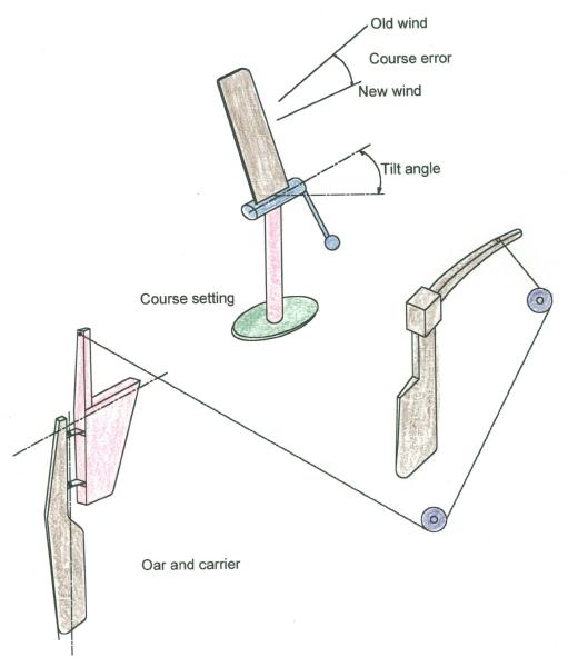
The wind vane-
The wind vane is some times called the "wind paddle" and as such is an appropriate label. The vane is mounted on a shaft to allow it to swing when the wind strikes at an angle and this provides a greater rotation than if it were a vertical axis vane and also produces much more torque about the shaft. This is the torque that sends a signal to the other parts of the system about the error and which way to turn the boat to correct it. The torque of the vane is transmitted to the oar via a linkage of pushrods or cables. The most important design point here is the need to keep friction at a minimum. As I show on the "Technical" page these wind generated loads are small. Just making the vane larger to get more torque can result in more friction and quickly negate the gain in vane output that finally gets to the oar's shaft.
The wind vane sizing is based on aeronautical data but it is also influenced by the space available on the boat. There are several options but a simple mast type works fine and can be braced off the stern rail or back stay if the support becomes too flexible. The airfoil data is closely related to model aircraft and at the small scale and wind speeds this is a good source of information. A simple thin flat plate will give almost as good a lift as cambered foils at the low angles of attack required. The flow at these speeds will be mostly lamina anyway. Some published data shows a large improvement if tabs are used on the trailing edges. My very preliminary wind tunnel tests do show that an advantage is found at angles of attack greater than five degrees and therefore should be considered. The tabs of about 20 % chord and set at 45 degrees in my tunnel tests showed complete separation and turbulence on the back side of the foil at about 5 degrees. This turbulence was large scale. Vortex size of 10 to 20 % of the chord. The flow leaving the trailing edge of the face side tab was also turning into the cavity of the tab mounting and was not at all smooth. I feel the initial increase in vane torque with the tabs is due to the increase in camber over a flat plate and the extra drag doesn't harm the torque so the net result is indeed a positive increase in vane torque. At high angles of attack the torque still continues to increase mostly due to the drag force causing a moment about the vane pivot shaft.
Mechanically the vane needs to be rugged. It will get whipped about in a strong wind and is also subject to being struck around docks. I think light weight plywood is a good compromise and it should be attached so it can be readily replaced with spares.
It is important to counter balance the vane so that the inertial loads of yawing or pitching from the boat don't introduce false signals to the system. Running in light air with little force on the vane from the wind and a passing motorboat wake can cause an unbalanced vane to send the boat on wild swings. Some over counter weighting of the vane may help stabilize the action on other courses so a provision to adjust this will help.
Sizing the vane is always a question. It must be large enough to drive the oar in heavy going and in light air. Experience has shown that vanes with areas about four square feet and aspect ratios near four are quite satisfactory. Using good bearings and holding the weight down, much smaller vanes can do the job. This is a good starting size in a design.Again, the example I show is only 1.25 square feet and works fine with the 20-20 model.
Oar and carrier-
The oar is the element that powers the system. It's action is often explained by holding a paddle edgewise in the water flowing past the boat and then twisting the handle to let the water strike the side of the paddle while trying to hold it in place. This resulting load transmitted to the tiller is what controls the boat. The force acting on the side of the oar is assumed to be centered about half way down the submerged blade and acting around the carrier's horizontal shaft axis. It is also desirable to have it acting close to the vertical hinge line of the oar. This is normally expected to be at about 25% back from the leading edge of a foil. However the underwater part of oar is in more complicated flow than most simple foil explanations show. The bottom tip and the water/air interface influence the loading. On most boats the wake will also be rather turbulent where the oar is operating. The center of gravity of the oar and it's shaft and the flotation of the blade should also act near the hinge line. A small amount of trailing is desirable. There will be a small vibration about the oar's hinge line called "Dither " by servo engineers. This is likely caused by the turbulent flow at the water / air surface. It is helpful in that it will help reduce the static friction the wind vane must overcome to turn the oar. While keeping the overall weight down is recommended the weight of this assembly is not much of a problem since even at flow speeds of one or two knots will provide enough side load to overcome an over weight design.
Output Linkage-
The water load on the oar will cause the carrier to rotate and move the output arm to supply the necessary line tension to the boat's tiller. With the sails properly trimmed this load will be the same as if the boat was being hand steered. The torque of the oar load about the carrier shaft will depend on the distance from the mid point of the submerged blade plus the distance from the water line to the carriers horizontal shaft. On most boats this will be on the order of four feet. An output arm of one fourth that will therefore give a line load capability of four times the oar load. This will far exceed most helmsman's strength. For this reason it is important to be able to disengage the self-steering very quickly.
Mechanically the oar needs to be light and stiff. Like much machine design ,the choices of materials will be the designer's personal preferences and many successful designs have used everything from stainless steel plate to wood . The size of the underwater part will be about two feet long and five to six inches wide. The blade foil profile should be well faired and have a smooth leading edge and sharper trailing edge. A NACA 0010 shape is often recommended for a good thickness and low drag profile shape.
Vane to rudder linkage ratios-
The ratios of the movements of the various elements interact to cause the error of off course to the wind to return the boat to the wind. A vane rotation to stops of about 45 degrees is enough. This vane rotation will be transferred to the oar and the amount of oar rotation about it's vertical axis will depend upon the geometry of the linkage. A one to one ratio will likely be more than needed and will contribute to over steer. This ratio needs to be adjusted to the ratio of the carrier swing to the boat's rudder turning. The oar carrier will swing to one side and as it does negative feed back will cause the oar angle of attack to lessen. This is negative feed back and a test of this important condition is easy to make. For an existing system installed on a boat at dockside hold the vane centered and check that the oar and the boat's tiller are inline with the boat's centerline. While holding the vane centered move the boat's tiller and notice the rotation of the oar. If the oar rotates in the same direction as the boat's tiller then the feed back is positive and WRONG . If it is right the output from the oar will be decreasing and the rudder load increasing until they balance out. The rudder angle will be at it's maximum for the oar's power and the boat will be returning to it's course setting. If the wind remains steady the relative wind angle will decrease on the vane and the smooth return to course will follow. High wind speeds and corresponding higher boat speeds will produce more load available to turn the rudder but if the rudder is badly balanced and has excess friction and line stretch the result will be less rudder angle and hence reduced response. In summary-- the vane/oar ratio of 1 to 0.25--.5 and the carrier swing/rudder of about 1.0 to 0.8 seems about the proper values to start the design with. These ratios define the static "Gain" . The final dynamic gain will likely be different due to inertial forces and fluid damping. This subject begins to get complex when all these factors are included in the design. As an example, I have not been able to find any data on the yaw damping of the turning rate for small boats. As always, experiment with your boat. You may find it requires different values for best performance. This is one reason I advocate building a cheap mock up version as a first model. It may seem a waste to use that approach but I find using 'experimental design ' to be easier to get a balance of all the variables needed to build a truly good self-steering device.
Summary The overall most important goal for a good design is keeping the friction low in the wind/linkage and avoiding mechanical complexities. The geometrical relations have been worked out by many builders and should be used as a starting point followed by test sailing to fine tune these values for the boat.
