This section is a collection of ideas and designs for consideration in deciding on a more advanced construction that may better fit the builders personal preferences. I have put them here to help reduce the size of the first Advanced page.
 14
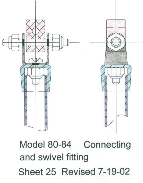
Typical push rod end fitting assembly for links.
The 1/2 inch CPVC cap is drilled for a
free turning fit and the Nylon insert
nut is adjusted to minimum end play
with free rotation.
14
Typical push rod end fitting assembly for links.
The 1/2 inch CPVC cap is drilled for a
free turning fit and the Nylon insert
nut is adjusted to minimum end play
with free rotation.
Notes and comments regarding the designing and building various prototype self-steering devices---
I find that building these designs as prototypes helps prove the drawings and often lead to changes and other ideas. Not all turn out as well as I had hoped but each helped the design of the next and are shown below for now.
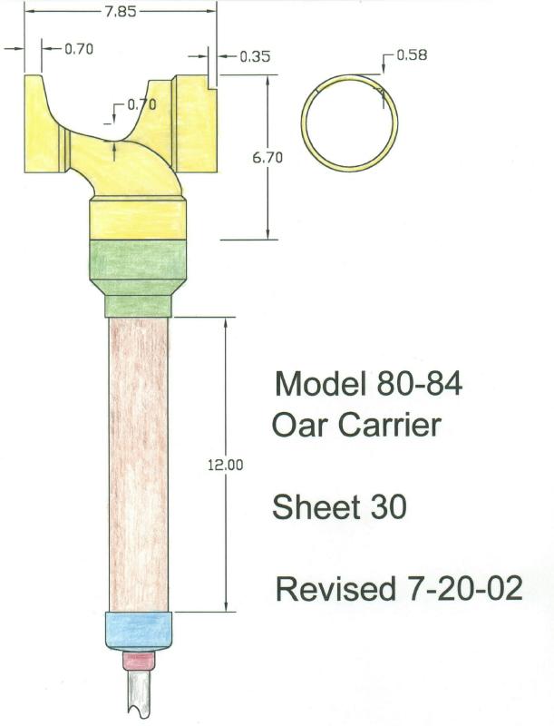
The photos are some of the ones builders have sent of their work and how they developed their models from some of my suggested designs. Sheet 30 I tested the thewear of the crank bearing on the PVC end caps using a five pound weight while the crank swings 45 degrees each way. This was agross over loading used to prove the life capability.
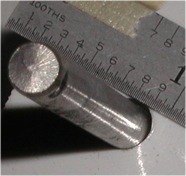
Photo number 66 shows the wear after 500,00 cycles.
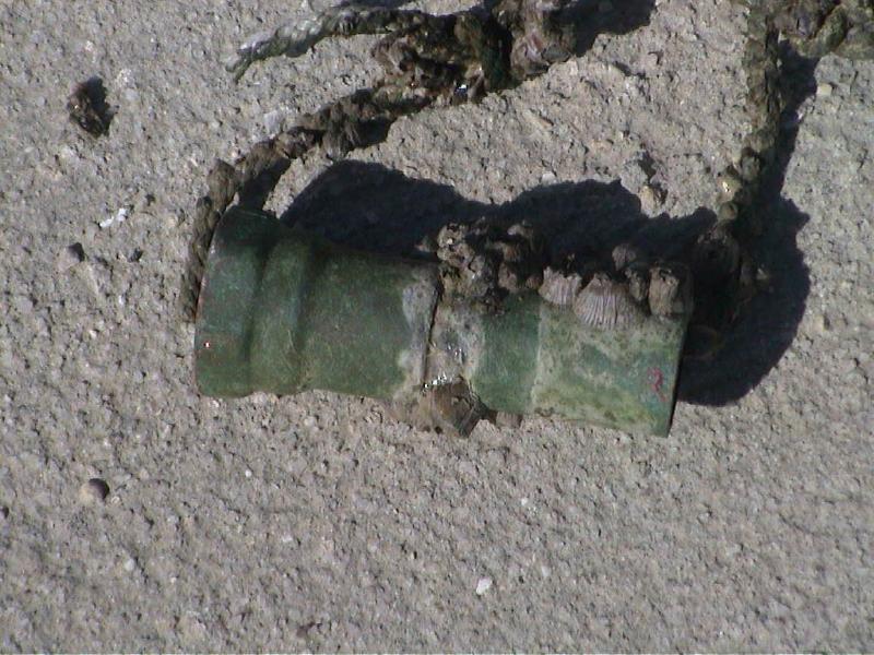
I have long term corrosion test under way with a sample of a bare copper pipe and fitting mounted in the tide line in Florida such that the tide covers and uncovers it. After about six months ( now November 2003 ) it is surely messy but appears to be structurally sound.
 37
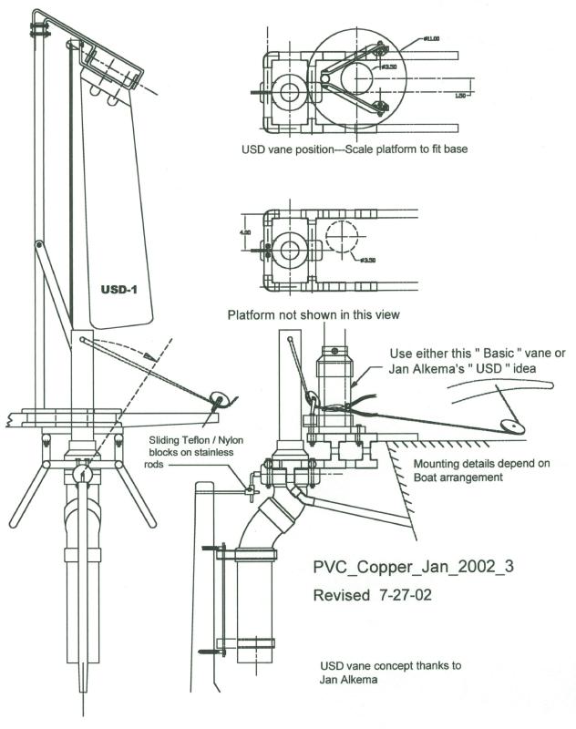
PVC_Copper_Jan_2002_3
This design was the basis of the version built by
Graig Cheek and shown in Photo # 72
I think he did a very good job of it.
37
PVC_Copper_Jan_2002_3
This design was the basis of the version built by
Graig Cheek and shown in Photo # 72
I think he did a very good job of it.
Photo 72
 38
38
Static test of a copper pipe to verify the yield strength.
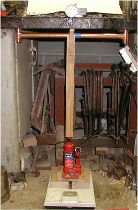 Test set up for a static bending test of a copper
pipe. 3/4 inch , Type L . The fittings are not soldered and the
repair sleeve is centered to spread the local loading.
The two tee fittings are centered 19 inches apart with the
tube inserted to the bottom of the cups. The dial indicator
was set post in place was used. This shows in the plot as a tare.
Notice that the beginning of the yielding is at about the 280 pound load.
Type "L" copper pipe is known in the USA as " Hard temper"
and will not be annealed by the soldering process.
A Google WWW search for Copper tube handbook
should yield a very good site regarding copper pipe soldering
techniques that will be helpful even If you happen to be
experienced with plumbing work.
Test set up for a static bending test of a copper
pipe. 3/4 inch , Type L . The fittings are not soldered and the
repair sleeve is centered to spread the local loading.
The two tee fittings are centered 19 inches apart with the
tube inserted to the bottom of the cups. The dial indicator
was set post in place was used. This shows in the plot as a tare.
Notice that the beginning of the yielding is at about the 280 pound load.
Type "L" copper pipe is known in the USA as " Hard temper"
and will not be annealed by the soldering process.
A Google WWW search for Copper tube handbook
should yield a very good site regarding copper pipe soldering
techniques that will be helpful even If you happen to be
experienced with plumbing work.
Try http://www.cerrocu.com/cda/book.html It was working as of 24 Jun 2003
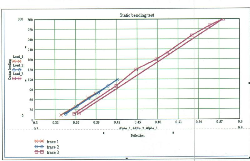 Test results for several loadings.
The
bending stress calculation confirms the yield strength
to be
in the range of 50,000 Psi. The plot shows a small set
after the maximum load was removed but it was not
discernable
by sighting along the tube axis.
Test results for several loadings.
The
bending stress calculation confirms the yield strength
to be
in the range of 50,000 Psi. The plot shows a small set
after the maximum load was removed but it was not
discernable
by sighting along the tube axis.
This tube was marked " Cerro STI Type L NSF-61 and was also incised marked very lightly.
 Chris Cel's very successful model done in
stainless steel. This first model uses a Z bar. A later one
used
bevel gears.
Chris Cel's very successful model done in
stainless steel. This first model uses a Z bar. A later one
used
bevel gears.
 The proof of Chris's gear.
 Gianello-2
 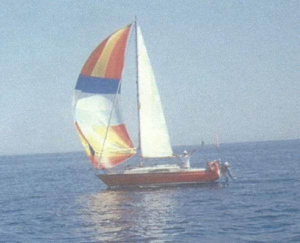 Adriatic Sea crossing.
I wish I could share Giancarlo's videos of this beautiful area.
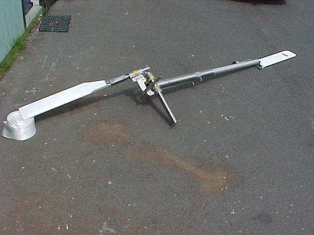
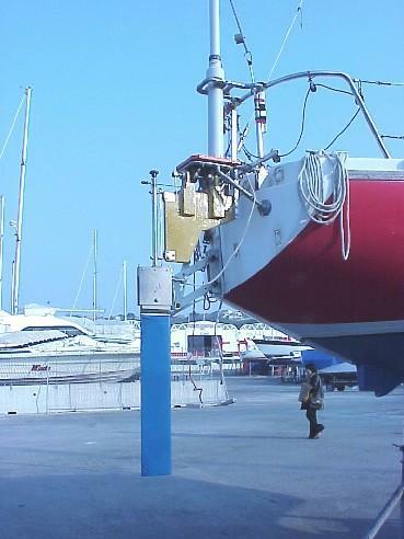
This is an interpretation of my 20-20 model that also used my
copper fitting suggestion. The builder was most pleased
with the results.
Adriatic Sea crossing.
I wish I could share Giancarlo's videos of this beautiful area.
This is an interpretation of my 20-20 model that also used my
copper fitting suggestion. The builder was most pleased
with the results.
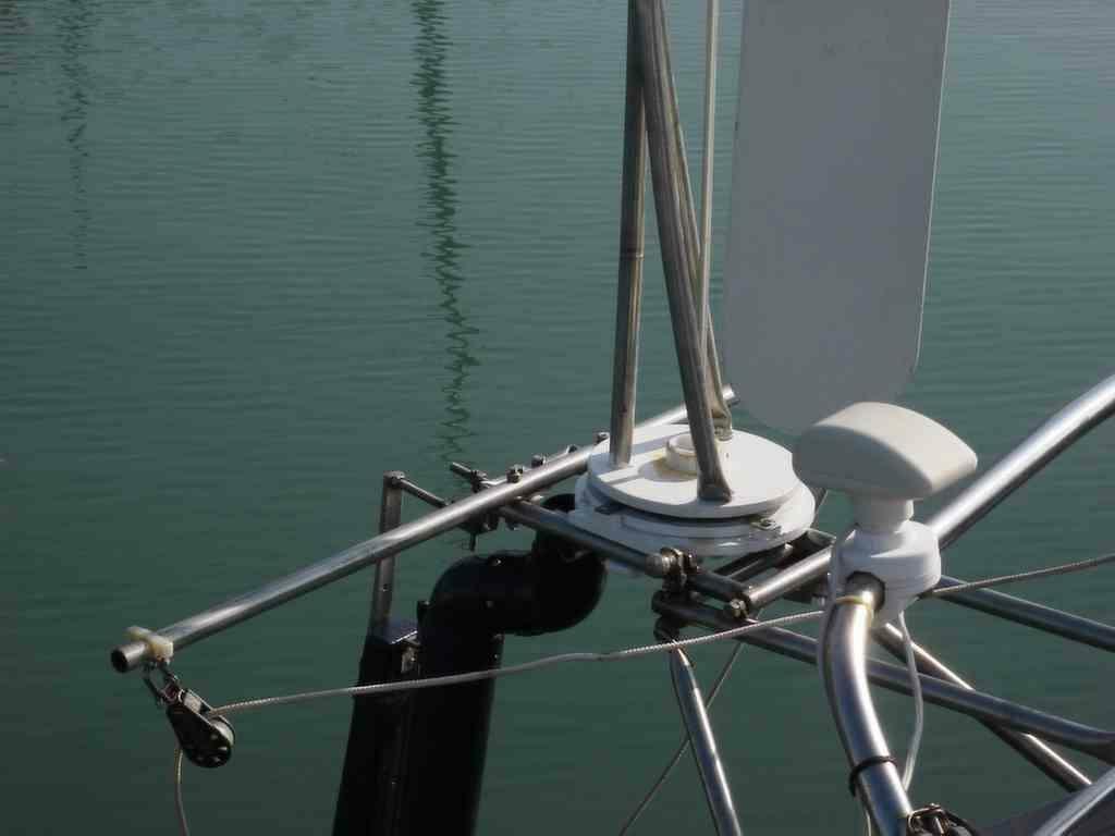
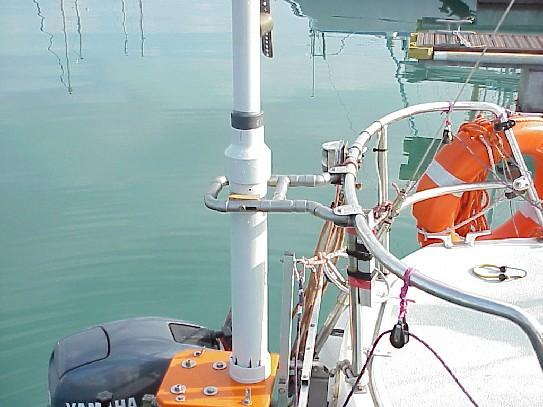 Close up of vane support and platform
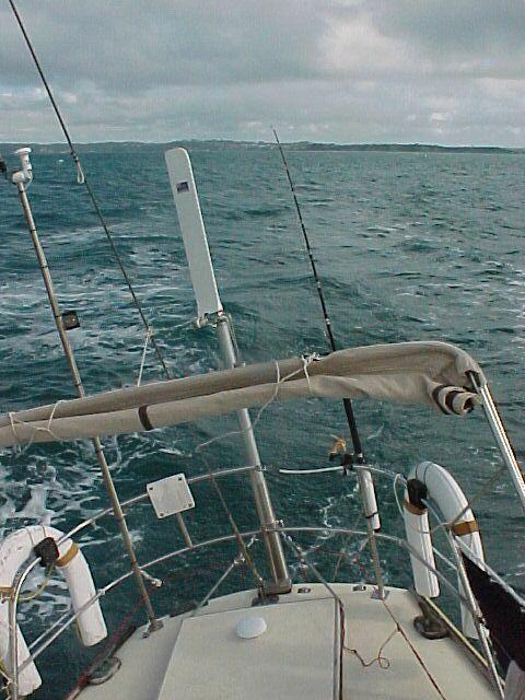
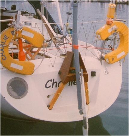 A very simple but excellent adaptation of my 20-20 basic
design on " Charlie B ".
The builder reported that he was quite pleased with the performance and I am pleased with the use
of the PVC and plywood mounting. This looks like my 20 hours, $20 , 20 Lbs has been met.
A very simple but excellent adaptation of my 20-20 basic
design on " Charlie B ".
The builder reported that he was quite pleased with the performance and I am pleased with the use
of the PVC and plywood mounting. This looks like my 20 hours, $20 , 20 Lbs has been met.
 42
This is
a recycled high school science project from one
of my
son's school days. I rescued it from the loft of our
shop and
cleaned out the squirrel nests to try some tests
of wind
vane design ideas. So far it is looking like it will be
useful. The
cross section is about 15 x 15 inches and the
present fan
gives about eight knots of very smooth flow.
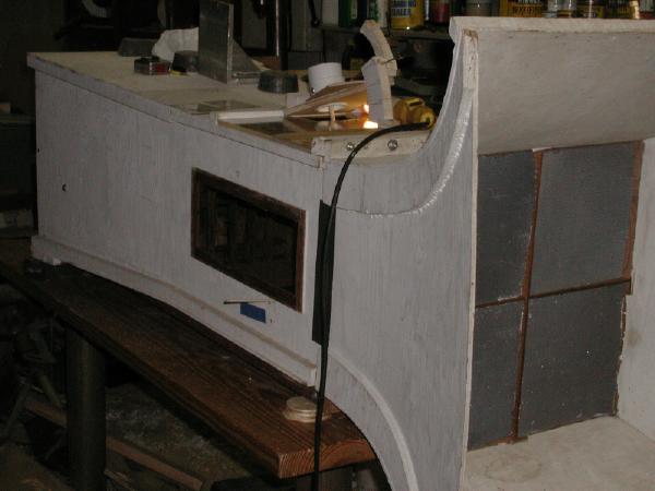
Originally this tunnel was set up to show airflow with
smoke
streamers and the turbulence was quite small.
It is one of
those " get to it some day " projects.
42
This is
a recycled high school science project from one
of my
son's school days. I rescued it from the loft of our
shop and
cleaned out the squirrel nests to try some tests
of wind
vane design ideas. So far it is looking like it will be
useful. The
cross section is about 15 x 15 inches and the
present fan
gives about eight knots of very smooth flow.
Originally this tunnel was set up to show airflow with
smoke
streamers and the turbulence was quite small.
It is one of
those " get to it some day " projects.
