The design of a self-steering device using the wind entails devising a means to convert the light air forces on a wind vane to an output line force capable of steering the boat. This is easily done by extracting power from the water flowing past the hull. This type of device is known as a type of servo system where the small input force from the wind vane is amplified to a line load large enough to control the boat. This magnification of load is referred to as " gain " and can be as much as several hundred timesthe input load from the wind vane. Getting this amplification is not difficult but getting it with out over steering is more difficult. The linkage action shown on the" Basic Action" page depicts some of the mechanical motion used to provide smooth control. The use of over counter weight of the wind vane and or an elastic line arranged to pull the vane to a neutral position can provide additional means of avoiding erratic steering.
The actual loads involved are surprisingly small and sample calculations below verify this.
The device needs no more output than is required to steer the boat by hand.
Check for errors in calculation and typing. Please report any you may find.
Theoretical Loading Calculations for Wind and Water Vanes
Wind Vanes Loading for a sample blade at a wind speed of 10 knots
Size ( Sv), 6 x 30 inches mounted such that the center of pressure is 16 inches above the rotation axis. 180 in2 /144 = 1.25 Ft2 Metric 1.25*0.0929 = 0.1161 M2 Angle of attack ( Alpha ) of 5.0 degrees. This assumes a 5 degree course error.
Gravitational constant ( G ) , 9.8 meters/sec/sec
Coefficient of lift ( Cl) , For ALPHA = 5.0 use Cl =0.5 ( Use this low value to help compensate for the low Reynolds number of such a small surface. Even this may be optimistic.
Air Density ( Da) = 1.215 Kg/M3
Velocity ( Va )= Wind speed in Knots , 0.5148 M/sec x Knots
Dynamic Pressure (Qa) = ( Density x Velocity2)/(2xG) At 10 Knots, Qa= 1.215 * ((0.5148)2 * (10)2)/(2*9.8)
Lift Force on Foil ( Lv) = Cl *Qa*Sv = 0.5*1.64*0.1161 = 0.095 Kg = 0.21 Lbs Comment--- This low incidence angle on the vane implies that most of the torque is being caused by the lifting effect such as an airplane wing would show. For a wind vane situation the drag loading becomes more of an influence at angles where the lift begins to stall. However, the result is that the torque actually continues to increase with more incidence even when the flow is in a stall condition.The incidence angle is determined by the off course error, the vane tilt, the boats heeling and any yawing or rolling so the calculation of the vane's output requires all these factors to be considered.
Oar loads
Oar loading at 7 knots boat speed in salt water
Size ( So) = 5 x 24 inches submerged blade = 120 in2 120 x0.0006452 = 0.077 M2
Cl= 0.7, for Alpha of 10 degrees
Dw =64 lbs/ft3 , 64x 16.02 = 1025.28 Kg/M3
Vo =(0.5148 x Knots) M/sec
Qw = 1025.28 x ((0.5148 x 0.5148 ) x (7 x 7 ))/(2 x 9.807) = 679 Kg/M2
Force on oar blade = 0.7 x 679 x 0.077 = 36.6 Kg , 36 X 2.205 = 81 Pounds
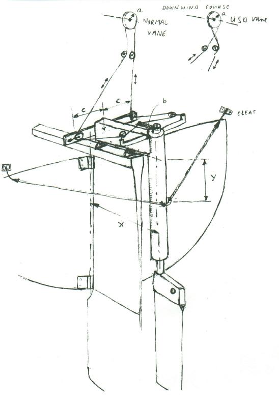
Insert sketch of push rod and oar crank here
Loads on the push rod and oar linkage.
Referring to the "Basic Action " page the calculated loading of the push rod and associated parts are:
For a force of 0.21 Lbs acting normal to the wind blade and having an effective center of pressure 15 inches above the vane's rotation axis with a moment arm of 15 inches produces a torque of (0.21 X 15 ) = 3.15in-lbs With an output crank arm of 1.5 inches ( A ) The push rod loading is : Pr= 3.15/1.5 , = 2.1 Pounds ( per the example above ). This push rod in turn acts on the crankshaft with an arm of 1.5 inches resulting in an input torque of 3.15 also neglecting the minor friction inthe link fittings The output side of the crankshaft which is twisting the oar about it's vertical axis is likewise causing 3.15 inch-lbs of torque on the oar axis.
For the rod that is bent to 45 degrees, Rotation of the oar for the full wind vane travel of 45 degrees is approximately 35 degrees. A bend of 30 degrees will rotate the oar some 22 degrees.
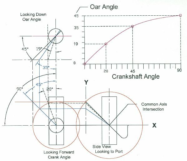
This should help explain the relationship of the crank to the oar rotation. Click on the thumbnail to enlarge. The geometry of the oar carrier and the slotted oar head will cause the oar to rotate back to zero angle of attack and align withthe streamflow past the hull. The power of the oar to steer the boat will require it to have enough force on it at the travel required to balance the load being producedby the boat's rudder.
For the case calculated above the angle of 10degrees angle of attack of the oar occurs when the 45 bent crank has rotated the carrier over about 25 degrees. For a 30 degree bend it would only swing over about 12 degrees to have this attack angle and equal load.
Reynolds Number The Reynolds number of the wind vane is calculated as follows:
Reynolds number equals velocity times the Chord length all divided by the Kinematic viscosity in feet per sec
Velocity = 10 (6070/3600) ft/
X= 0.5 Feet of chord length
v=0.0001567 ft2/sec
R = V (X/v)
R = 5.38x10⁴
At these low values the flow will be all lamina and simple flat plate sections will be almost as good as more curved foils.
PVC and sunlight. This is a question that comes up quite often and from my personal experience and searching the net has found no problem with the physical properties of PVC piping and fittings made to USA ASTM D 1784/5 specifications. However ,there is no doubt that many mixes referred to as " PVC " that will not qualify. In countries where the quality is not very good the builder should look for local knowledge and paint any exposed pipe.
Jan Data_1 These files were posted on the forum
 Showing (-) 30 degree tilt axis
 Showing wake running straight downwind
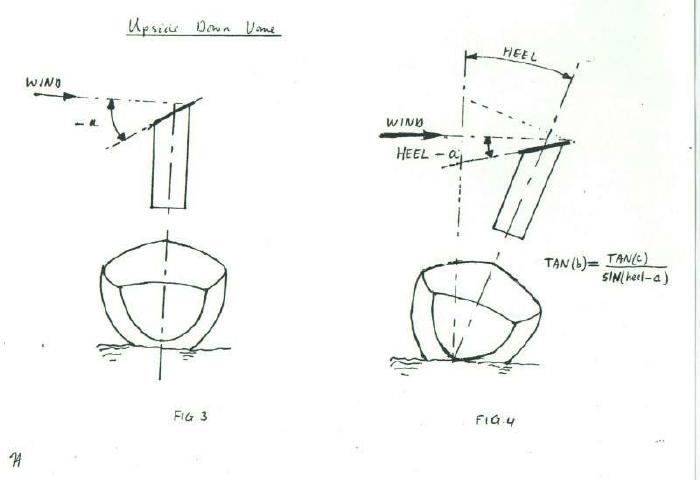
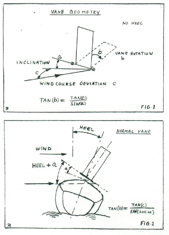 Normal vane geometry
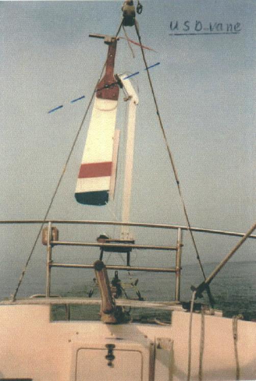
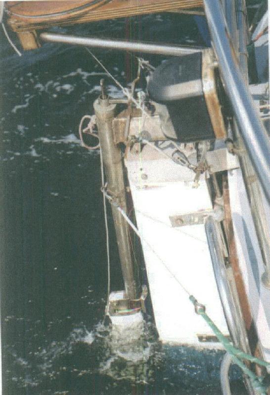
 USD vane geometry
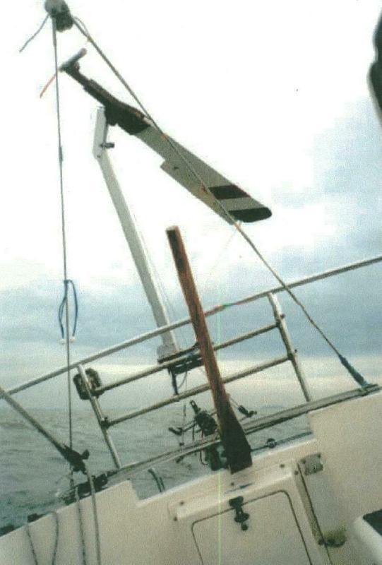
 Jan's oar working
 Jan's rudder
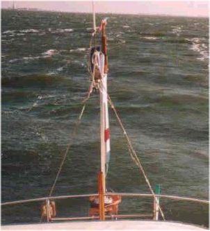
 Heeled
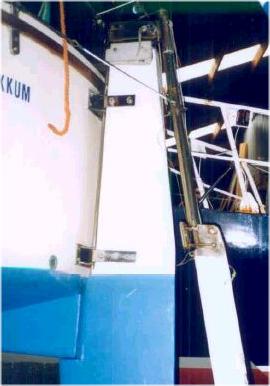
 Jan's wire rig
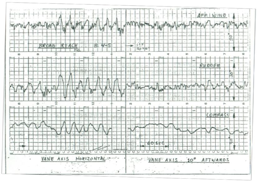
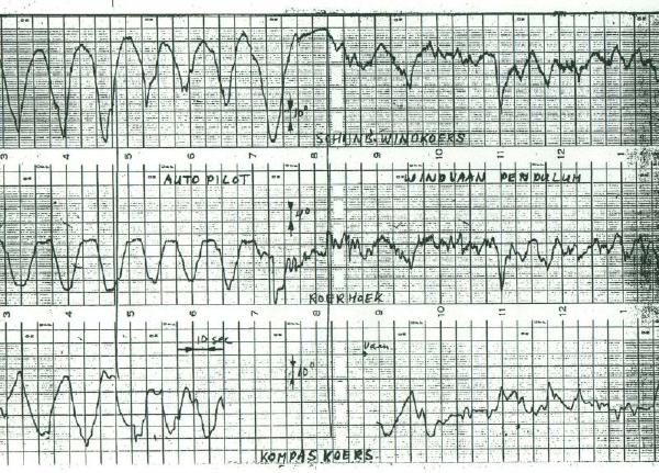 Auto Vs Vane system recording
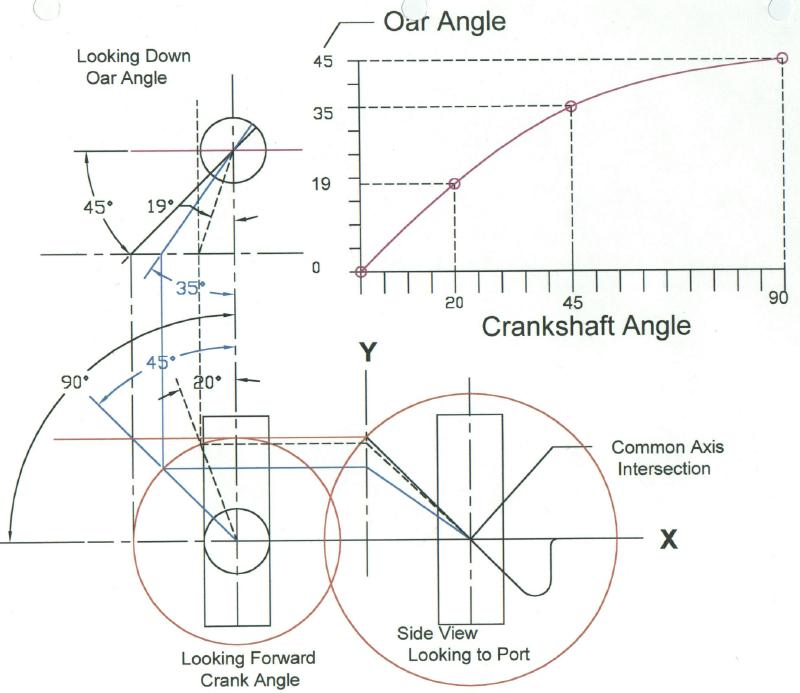 Z bar crank Vs oar angles
 Jan July 2003
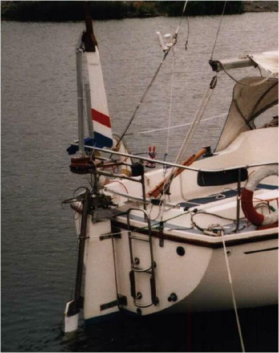 Jan's boat with USD and RHM
