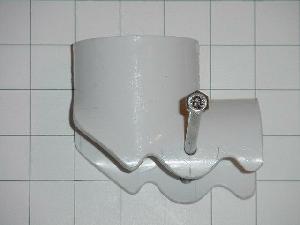
Photo 1 Click on thumbnails to enlarge image. Use back button to return
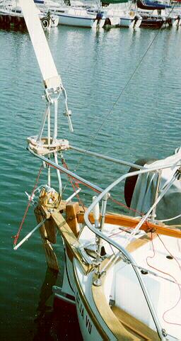 This design was the arrangement that inspired
the need to design a simple to build version. It surely was not simple.
This design was the arrangement that inspired
the need to design a simple to build version. It surely was not simple.
Photo 3
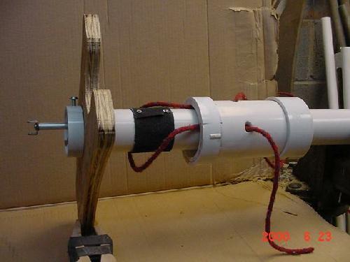
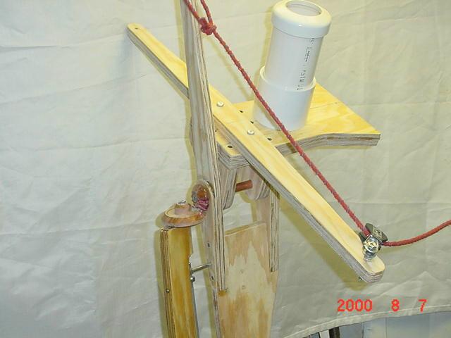 This version under construction is shown with two bevel
gears rather than the "Crooked" crankshaft and PVC pipe. Gears
might be a better way for some builders. A ratio of two to one is good
and with careful alignment of the gears should result in low friction.
This version under construction is shown with two bevel
gears rather than the "Crooked" crankshaft and PVC pipe. Gears
might be a better way for some builders. A ratio of two to one is good
and with careful alignment of the gears should result in low friction.
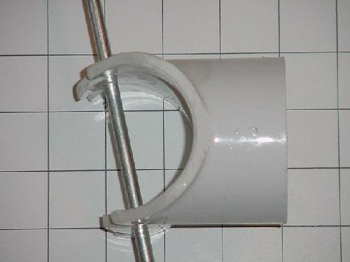
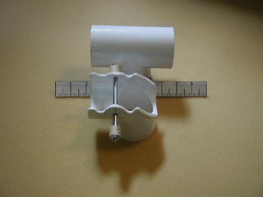
Photo 2
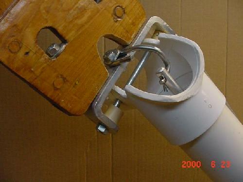
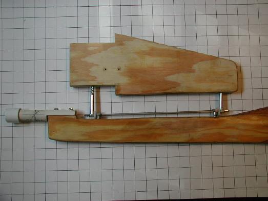
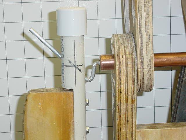 This detail is the heart of this design. The action of the bent rod working in
the slot of the short section of PVC pipe turns the
oar blade to cause it's carrier to rotate due to the flow past the hull
and generate the force needed to steer the boat. The position of the three
rotation axes also provides for the necessary feed back for smooth control.
This detail is the heart of this design. The action of the bent rod working in
the slot of the short section of PVC pipe turns the
oar blade to cause it's carrier to rotate due to the flow past the hull
and generate the force needed to steer the boat. The position of the three
rotation axes also provides for the necessary feed back for smooth control.
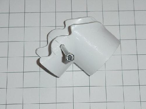
Photo 4
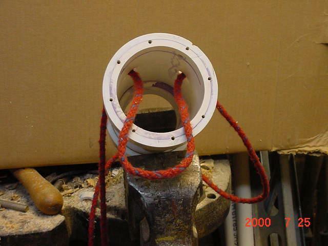
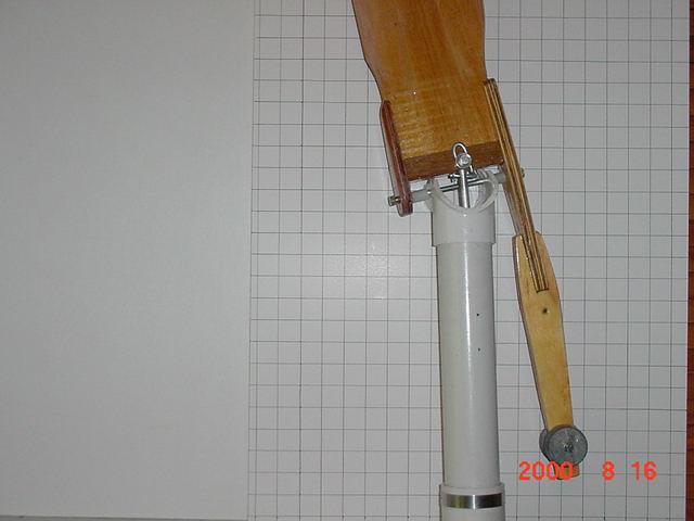
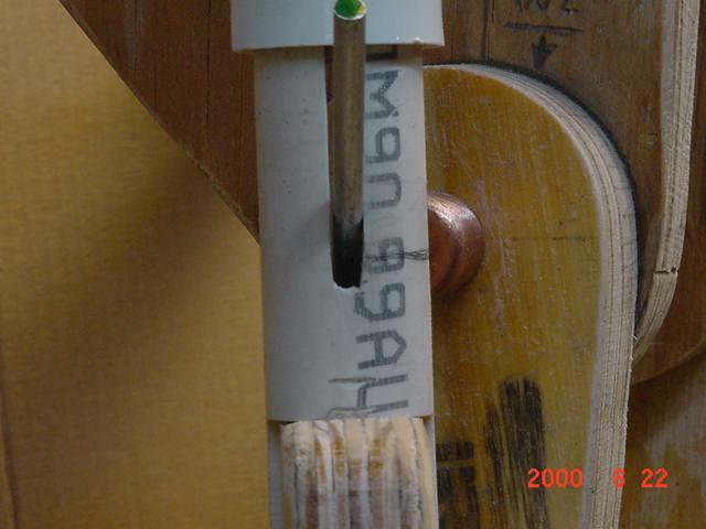 This shows the crankshaft turned to the full extent of the
travel allowed by the wind vane's 45 degree rotation.
This shows the crankshaft turned to the full extent of the
travel allowed by the wind vane's 45 degree rotation.
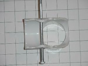
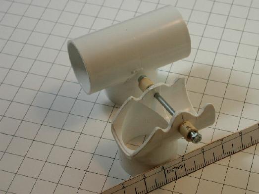
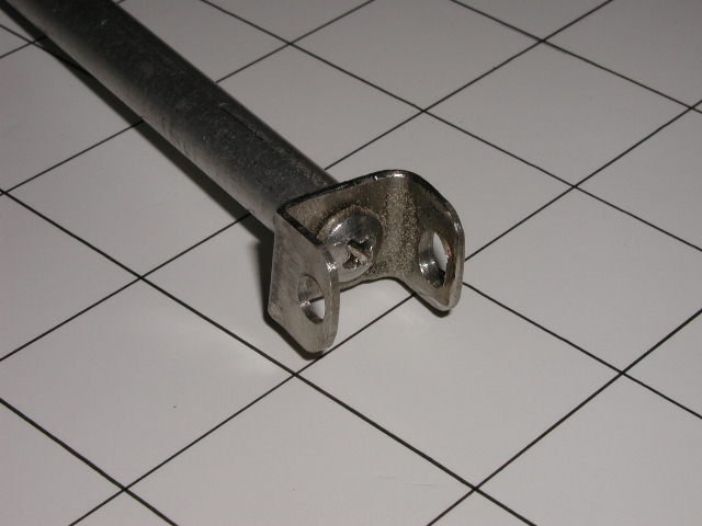
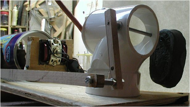
Photo 70
 A stainless steel tube rather than a PVC one.
This is not much more difficult to fabricate. Take care to get
good alignment to avoid binding on the shaft.
A stainless steel tube rather than a PVC one.
This is not much more difficult to fabricate. Take care to get
good alignment to avoid binding on the shaft.
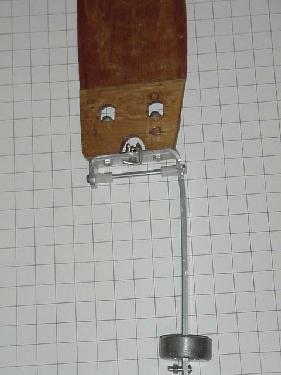
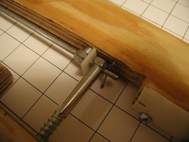
 For an even simpler version--Use hardwood blocks well
greased
and aligned with the bent shaft as shown. The "Z" bar in this
photo is also easier to bend than the one in Photo 5 below.
The loop part allows the start of the angled leg to be
accurately bent. The Oar axis and the carrier pivot axis must
intersect at the red spot and both must intersect at the same
point in the vertical plane. There should be no binding in either
direction and minimum free play from the vane to the oar.
For an even simpler version--Use hardwood blocks well
greased
and aligned with the bent shaft as shown. The "Z" bar in this
photo is also easier to bend than the one in Photo 5 below.
The loop part allows the start of the angled leg to be
accurately bent. The Oar axis and the carrier pivot axis must
intersect at the red spot and both must intersect at the same
point in the vertical plane. There should be no binding in either
direction and minimum free play from the vane to the oar.
Photo 5
 A
dummy part made as a photo "prop" to illustrate the
bend and angles of the crankshaft part. The input and output are
90 degrees apart on the real version and the straight shaft section
is also longer than shown here. See the "More Photos" page for
a series of how to bend pictures.
A
dummy part made as a photo "prop" to illustrate the
bend and angles of the crankshaft part. The input and output are
90 degrees apart on the real version and the straight shaft section
is also longer than shown here. See the "More Photos" page for
a series of how to bend pictures.
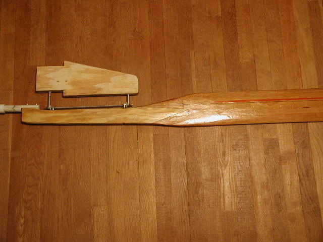
Photo 6
 The
vane is made of any light, stiff wood such as fir plywood.
The cheek pieces are
glued on and provide a mounting base for
bolting it to the carrier bar.
Several builders have reported the need to increase the area of
this design by about 50 %.
The
vane is made of any light, stiff wood such as fir plywood.
The cheek pieces are
glued on and provide a mounting base for
bolting it to the carrier bar.
Several builders have reported the need to increase the area of
this design by about 50 %.
Photo 7
 The
carrier and counter weight bar is made from either
an aluminum bar or a thinner steel bar of the same width. The counter weight will be about two pounds of lead that is adjustable up and down
the bar for fine
tuning the system's response in light air conditions.
The
carrier and counter weight bar is made from either
an aluminum bar or a thinner steel bar of the same width. The counter weight will be about two pounds of lead that is adjustable up and down
the bar for fine
tuning the system's response in light air conditions.
Photo 8
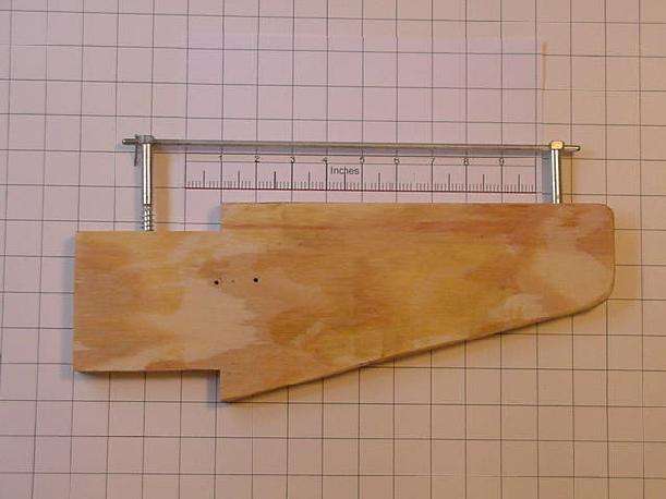
 This
"exploded" view shows the course setting line and the mast support.
The platform here is shaped to fit the boomkin
on the boat in photo number 1. The black ban is a section of abrasive
cloth to provide friction for the course sitting line.
This
"exploded" view shows the course setting line and the mast support.
The platform here is shaped to fit the boomkin
on the boat in photo number 1. The black ban is a section of abrasive
cloth to provide friction for the course sitting line.
Photo 9
 Vane
support detail showing the vane crank fitting
and upper end of the push rod.
Vane
support detail showing the vane crank fitting
and upper end of the push rod.
Photo 10
 The
base of the mast support with the course setting
line showing the mounting screw holes.
The
base of the mast support with the course setting
line showing the mounting screw holes.
Photo 15
 Cut from a schedule 40 PVC pipe Tee fitting
Photos 16 17 18 21 23
Photos 11
12
13
14
23
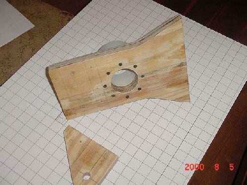
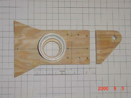
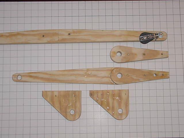
 Plywood parts for platform and oar carrier shown over a one inch grid
board
Plywood parts for platform and oar carrier shown over a one inch grid
board
Photo 20
 An all wood vane and carrier.
Photo 27
 Detail of lower end of push rod. Note this fitting is
free to rotate around the screw to allow the vane to be set
to the desired course.
Detail of lower end of push rod. Note this fitting is
free to rotate around the screw to allow the vane to be set
to the desired course.
Photo 28
 The oar shown here has no provision for kick up
or release in the event it catches on something. For use in
serious cruising a means of relieving the load should be used.
A simple hinged blade held in a detent will work well.
See Photo 25 for one way to do this.
The oar shown here has no provision for kick up
or release in the event it catches on something. For use in
serious cruising a means of relieving the load should be used.
A simple hinged blade held in a detent will work well.
See Photo 25 for one way to do this.
Photo 29
 Detail of the Lag bolt hinges and rod.
Photo 25
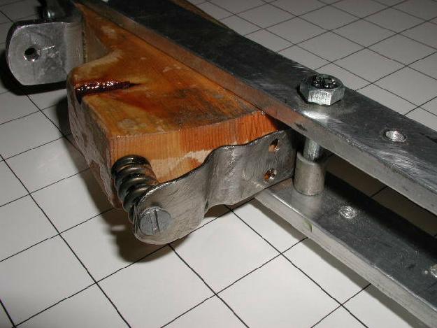 Spring loaded kick up blade mounting device.
Photo 65
 Life testing of stainless crank swinging 45 degrees
either side of vertical turning in a PVC pipe fitting loaded with
a five pound lead weight. Photo made after about 35 minutes
of run time. Test cycling 14 cycles per minute
Life testing of stainless crank swinging 45 degrees
either side of vertical turning in a PVC pipe fitting loaded with
a five pound lead weight. Photo made after about 35 minutes
of run time. Test cycling 14 cycles per minute
Photo 66
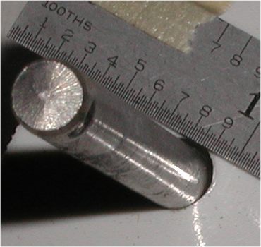 Wear after 500,000 cycles. I scale this egging to be
about 0.04 inches and insignificant for the loading and number of
cycles run with no lubrication.
Wear after 500,000 cycles. I scale this egging to be
about 0.04 inches and insignificant for the loading and number of
cycles run with no lubrication.
