These are miscellaneous photographs of related details and and fabrication ideas.
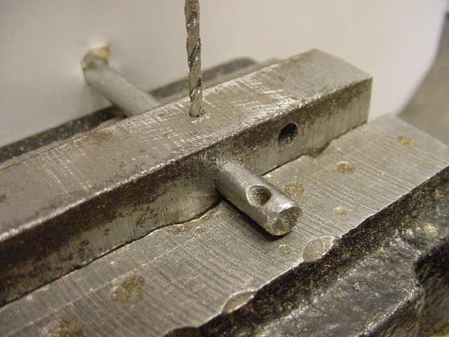 Photo 19
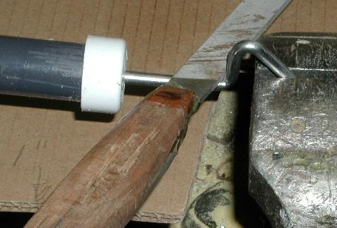
Simple drill jig to aid in drilling a small hole in the shafts
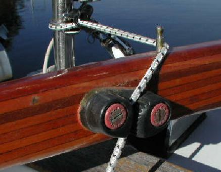 Photo 39
Cam cleats on tiller for quick setup/release.
The elastic cord was just for the photograph to illustrate the line run.
A simple length of chain that drops down on a pin has been used for this function.
Photo 30
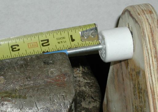
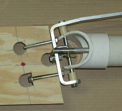
.....An alternative to a PVC pipe fitting
 This is a metal bar mounted on a coupling fitting as a vane support carrier. No stops are shown in this photograph but they can be fitted
to limit the swing of the counterweight arm.
This is a metal bar mounted on a coupling fitting as a vane support carrier. No stops are shown in this photograph but they can be fitted
to limit the swing of the counterweight arm.
Photo
31 ....
Another view
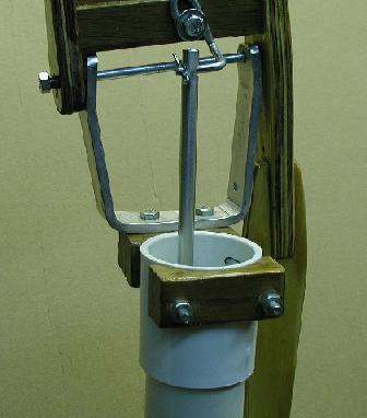
Photo 32 Bending the Crankshaft
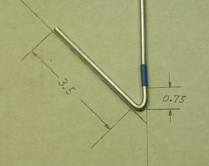 The first bend is made to a 45 degree angle and
and the next bend start position marked. That is show here at the
lower edge of the blue masking tape.
The first bend is made to a 45 degree angle and
and the next bend start position marked. That is show here at the
lower edge of the blue masking tape.
Photo 33 The first stage in the forming of the second bend
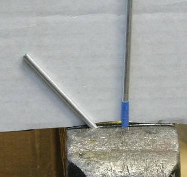 Clamp the rod as shown and make the first part of the
bend at an angle to the vise as shown in the next photo
Clamp the rod as shown and make the first part of the
bend at an angle to the vise as shown in the next photo
Photo 34 Next stage of the bending
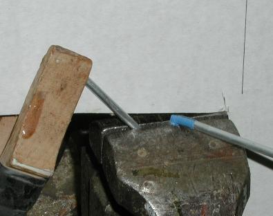 The exact angle of this bend is not important.
the purpose is to minimize the twisting or bending required to
finish the oar end bending.
The exact angle of this bend is not important.
the purpose is to minimize the twisting or bending required to
finish the oar end bending.
Photo 35 Straitening the shaft and final bend on this end.
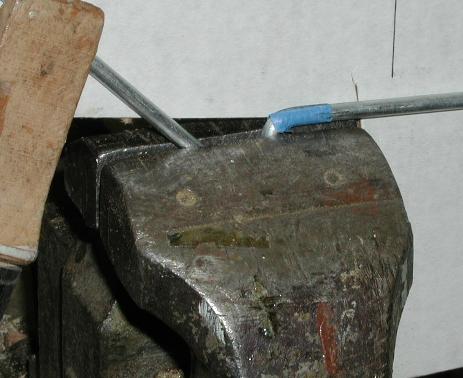 Twist or bend the shaft into the same plane as the first bend.
Photo 36 Trimming the burrs if any
 File the shaft round and polish out any forming burrs that might have been made.
Photo 37 Bending the push rod end
 This series of bends are made after the pivot
shaft has been made. The purpose in the extended crank is to
provide clamping room with the rod inserted in the pivot shaft.
This series of bends are made after the pivot
shaft has been made. The purpose in the extended crank is to
provide clamping room with the rod inserted in the pivot shaft.
Photo 71
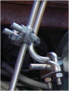 This use of U-clamps came from feedback from a new builder who reports they work very
well and allow adjustments. In this photo they are being used to support a vane. Another
builder variation on how to solve a problem.
Photo 71
This use of U-clamps came from feedback from a new builder who reports they work very
well and allow adjustments. In this photo they are being used to support a vane. Another
builder variation on how to solve a problem.
Photo 71
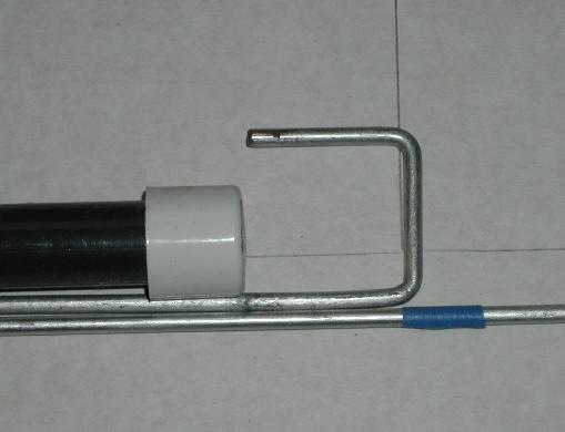
Photo 38 The crank input is in a plane 90 degrees to the oar end output rod.
 A stopper tube will prevent this shaft moving
fore and aft and disturbing the alignment with the oar head.
A stopper tube will prevent this shaft moving
fore and aft and disturbing the alignment with the oar head.
Photo 40
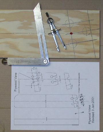 Layout of the attachment end of a plywood vane showing the layout of the three
one inch holes to be cut.
The red spot is the reference point shown on the vane drawing.
Layout of the attachment end of a plywood vane showing the layout of the three
one inch holes to be cut.
The red spot is the reference point shown on the vane drawing.
Photo 41
 Here the holes have been cut and one slot cut for the attaching bolt. These
slots will be cleaned out with a drill
after the two cheek pieces are glued in place. The base will
be sawn flat and square to clamp to the carrier bar part.
This will be a very stiff and strong attachment.
Trim the excess vane material to blend with the carrier.
Here the holes have been cut and one slot cut for the attaching bolt. These
slots will be cleaned out with a drill
after the two cheek pieces are glued in place. The base will
be sawn flat and square to clamp to the carrier bar part.
This will be a very stiff and strong attachment.
Trim the excess vane material to blend with the carrier.
Photo 42
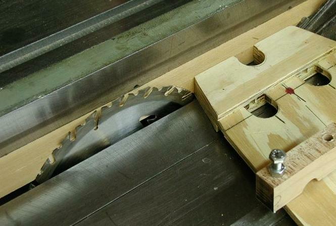 Set up on table saw to cut end square and flat
with the carrier pitch angle per layout.
Set up on table saw to cut end square and flat
with the carrier pitch angle per layout.
Photo 46
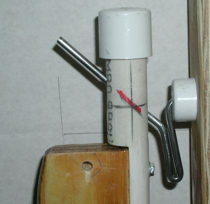 This shows how little the misalignment of the axes
with the slot in the PVC pipe can cause a slight binding of the
oar rotation to the detriment of the systems performance in light
air conditions.
This shows how little the misalignment of the axes
with the slot in the PVC pipe can cause a slight binding of the
oar rotation to the detriment of the systems performance in light
air conditions.
Photo 61
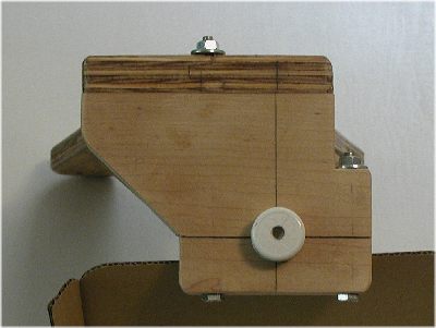 This alternate hanger allows for the removal of the lower assembly and oar
carrier
crankshaft.
This alternate hanger allows for the removal of the lower assembly and oar
carrier
crankshaft.
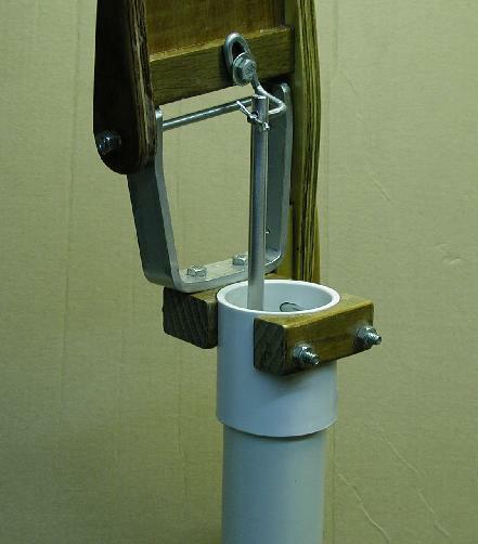
Photo 62
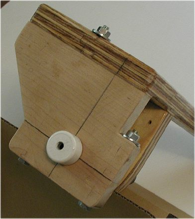 Another view. The cap blocks
remove along the horizontal line through the
pivot shaft. This shows a 1/2 inch PVC cap
being used as the crankshaft bearing and
a schedule 80 , black PVC pipe as the pivot.
Another view. The cap blocks
remove along the horizontal line through the
pivot shaft. This shows a 1/2 inch PVC cap
being used as the crankshaft bearing and
a schedule 80 , black PVC pipe as the pivot.
